L-type equivalent circuit and parameters for a continuous sinusoidal phase of a 5.5 kW, 1420 rpm, line voltage 220 V and frequency 50 Hz star-connected 3-phase ASM, ignoring core (iron) losses given as follows: R1=0.21 Ohm, R2=0.18 Ohm, X1=X2=0.66 Ohm and Xm=9.9 Ohm i, i, R, R, jX m (1-s) S How many times the rated current will the inrush current be when the ASM is started directly? O 3.7473 O 1.2558 O 6.3414 O 8.0815 O 7.1534 O 2.6455 n 4.3763
L-type equivalent circuit and parameters for a continuous sinusoidal phase of a 5.5 kW, 1420 rpm, line voltage 220 V and frequency 50 Hz star-connected 3-phase ASM, ignoring core (iron) losses given as follows: R1=0.21 Ohm, R2=0.18 Ohm, X1=X2=0.66 Ohm and Xm=9.9 Ohm i, i, R, R, jX m (1-s) S How many times the rated current will the inrush current be when the ASM is started directly? O 3.7473 O 1.2558 O 6.3414 O 8.0815 O 7.1534 O 2.6455 n 4.3763

Power System Analysis and Design (MindTap Course List)
6th Edition
ISBN:9781305632134
Author:J. Duncan Glover, Thomas Overbye, Mulukutla S. Sarma
Publisher:J. Duncan Glover, Thomas Overbye, Mulukutla S. Sarma
Chapter3: Power Transformers
Section: Chapter Questions
Problem 3.52P

Related questions
Question
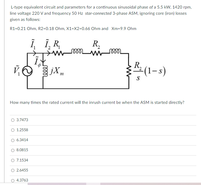
Transcribed Image Text:L-type equivalent circuit and parameters for a continuous sinusoidal phase of a 5.5 kW, 1420 rpm,
line voltage 220 V and frequency 50 Hz star-connected 3-phase ASM, ignoring core (iron) losses
given as follows:
R1=0.21 Ohm, R2=0.18 Ohm, X1=X2=0.66 Ohm and Xm=9.9 Ohm
Î, Î, R
R,
ண
jXm
R,
(1-s)
S
How many times the rated current will the inrush current be when the ASM is started directly?
3.7473
O 1.2558
6.3414
8.0815
O 7.1534
O 2.6455
4.3763
Expert Solution
This question has been solved!
Explore an expertly crafted, step-by-step solution for a thorough understanding of key concepts.

Step by step
Solved in 4 steps

Recommended textbooks for you
Power System Analysis and Design (MindTap Course …
Electrical Engineering
ISBN:
9781305632134
Author:
J. Duncan Glover, Thomas Overbye, Mulukutla S. Sarma
Publisher:
Cengage Learning
Power System Analysis and Design (MindTap Course …
Electrical Engineering
ISBN:
9781305632134
Author:
J. Duncan Glover, Thomas Overbye, Mulukutla S. Sarma
Publisher:
Cengage Learning