For the system shown in figure, voltage V2 and angle 8, are calculated using Newton-Raphson method. Calculate the complex power flow at both the ends, i.e., S12 and S21. Also calculate the power loss Soss in the transmission line. All the units are in per unit. Z12= 0.02 + j0.04 PL2 QL2 Slack bus V=1.0/0° pu V2=0.905-6.34
Q: A 230-kV, 100-km, 60-Hz three-phase overhead transmission line with a rated current of 900 A/phase…
A: Transmission line- The term transmission line refers to both overhead and underground cables. An…
Q: 1. What are the factors which governs the performance of transmission line? 2. How do you classify…
A: 1..>> The performance of the transmission line depends on parameters like :- Resistance of…
Q: Describe the effect of mixed load (resistive + inductive) on sending and receiving end voltages,…
A: Effect of (resistive + inductive) on sending and receiving end voltages. Tran mission line can be…
Q: The load flow data for a three-bus system is given below. Taking bus 1 as the slack bus, determine…
A:
Q: Q1/ Equipment ratings for the four-bus power system shown in Figure are as follows: Generator G1:…
A:
Q: QUESTION 1: For the 3-ph, double circuit O.H.T.L shown below: 1- Find the spacing between the two…
A: According to question, For the 3-ph, double circuit O.H.T.L shown below: 1- Find the spacing between…
Q: For the power system shown at right the impedance matrix (2 is j0.4 3 j0.5 j0.2 0.164 0.101 0.0692…
A:
Q: What is the need to conduct power flow analysis? Discuss about data needed and bus types too.
A:
Q: Q1: For a medium line model, draw the circle diagram only and put the value of OR, OS and 0t If you…
A: Three-Phase Line: Three-phase alternating current is a popular form of alternating current used in…
Q: a. Find the Real Power, Reactive Power and power factor characteristics of the load. b. Show the…
A: In the question, Find the Real Power, Reactive Power and power factor characteristics of the load…
Q: At the end of the 8 km overhead line given in the figure below, there are two distribution…
A: According to question: The currents 'I1' and 'I2' in the distribution transformers are calculated as
Q: A 500-kV, 300-km, 60-Hz three-phase overhead transmission line,
A: Insulator in transmission line- The device used to protect transmission line and prevent the…
Q: A 3-ph transmission line has a total length of 200 km. This transmission line has a resistance of…
A:
Q: . Contribution of load flow studies to erect new power station?
A:
Q: a) Discus why the transmission systems are mostly overhead systems. b) Discuss why all overhead…
A: a) The transmission systems are mostly overhead systems: Electrical power transmission is the…
Q: Problem 2.. Determine the 3×3 bus admittance matrix Yous for the 3-bus circuit in the figure below.…
A: Given circuit diagram, YBUS =?
Q: Q3: A synchronous generator with peak generated voltage Vg which is connected to a lighting arrester…
A: Equivalent per phase diagram Apply KVL in loop 1)
Q: a) Discus why the transmission systems are mostly overhead systems. b)Discuss why all overhead lines…
A: ACSR- Aluminium conductor steel-reinforced cable Bundled conductors- When a single phase conductor…
Q: 1: Establish Zbus matrix for the system shown in figure below using Direct Method and add the lines…
A: Given: Consider the following circuit: To find: Establish the Zbus matrix for the system shown in…
Q: The Gauss-Seidel is an iterative method used to solve a set of nonlinear equations in the power…
A: Gauss-Seidel method is used to solve the power flow analysis question in the power system. In two…
Q: Subject: Electrical & Electronics Engineering Course: Power Systems Question: In case of modeling…
A: Modeling a Long Transmission Line, procedures :- Physical ACSR conductor is replaced with…
Q: a). What is the reason for providing sag in an Overhead transmission line? b). List any two…
A: Whenever there is a need to send electricity to far off long distances, then the usage of overhead…
Q: Example 4: Determine the efficieney and regulation of a 3-phase, 100 km, 50 Hz transmission line…
A: Transmission lines with lengths lying between 80 km to 160 km are categorised as medium length…
Q: The figure below shows the one-line diagram of a simple three-bus power system with generation at…
A:
Q: 2. Contribution of load flow studies to erect new power station?
A: A power system is modelled by an electric network and solved for steady state power and voltages at…
Q: a) Draw impedance diagram in per unit, by using 100-MVA base. Select 20kV as the base voltage for…
A: You have asked multiple independent questions. We are authorized to answer one question at a time.…
Q: A single-line diagram of a four-bus system is shown in fiugre. Equipment ratings and per-unit…
A: Given: A single-line diagram of a four-bus system is shown below: Machines 1 and 2: 100 MVA 20 kV;…
Q: (k) Determine the economical cross-sectional for a single phase transmission line, 1 km transmission…
A: For the 3 phase transmission line of 1 km and a voltage of 110 kV. Thus, the load cycle is, 6 hr 20…
Q: By using Gauss-Siedal method, the voltage of the bus 2 after two iteration is By using Gauss-Siedal…
A: Initial guess values are:V1=1+j0V2(0)=1+j0V3(0)=1+j0Injected power into the system is:P2=-0.6 ,…
Q: following figure shows the one-line diagram of a power system. Bus 1 is selected as a reference bus…
A: Solution- Given, V1 = 1 + j(0) Z = 0.02+ j0.04 p.u. S2 = 280 MW + j60 Mvar
Q: Example 4: Determine the efficiency and regulation of a 3-phase, 100 km, 50 Hz transmission line…
A: According to the question we have to find the value of efficiency and regulation with the help of…
Q: 2. The load flow data for a three-bus system is given below. Taking bus 1 as the slack bus,…
A: The load flow data for a three bus system is given below. As Bus1 is a slack bus…
Q: Figure 3 shows the one-line diagram of a three-bus power system with generation at bus X. The…
A:
Q: QI/A: The per unit admittances are indicated at the diagram and the bus data are given in table as…
A: YBUS=Y11Y12Y13Y21Y22Y23Y31Y32Y33where,Y11=y12+y13Y12=Y21=-y12Y13=Y31=-y13Y22=y12+y23Y23=Y32=-y23Y33=…
Q: From the system as shown below with base of 100 MVA by neglecting all parallel admittance. (a)…
A: Since there is two bus in the system, so Size of Ybus matrix will be 2×2.…
Q: The equivalent circuit of a single phase short transmission line is shown in Figure Q4 (b). Here,…
A: Short Transmission Line: Generally there are three types of Transmission line in power system…
Q: 916: The sending end and receiving end voltages of overhead line at 120 MWw load are equal at 110…
A:
Q: Q3: A synchronous generator with peak generated voltage Vg which is connected to a lighting arrester…
A: 1) Peak value of the generated voltage of the synchronous generator= Vg RMS value of the generated…
Q: A lossless TL with characteristic impedance of to is terminated in Zv=3Z0. use crank diagram to…
A: Since you have asked multiple questions, we will solve the first question for you. If you want any…
Q: The figure below shows the one-line diagram of a four- bus power system. The voltages, the scheduled…
A: Note: We are authorized to answer three subparts at a time since you have not mentioned which part…
Q: . Which one of the following method uses weak coupling between reactive power and voltage angle?. A.…
A:
Q: Plot generator output voltage versus load current for operating conditions with and without…
A: Voltage regulator is a circuit designed to maintain constant voltage at the output. The following…
Q: In an over head transmission line the conductor weight with ice loading is 2.35 kg. The total weight…
A: As per bartleby guideline for more than one question asked only first is to answered please upload…
Q: One of the following load flow analysis method is not more efficient for large power systems.…
A: Gauss- Seidal Method
Q: In the power system network shown in Figurebelowbus 1 is a slack bus with V = 1.020° per unit and…
A: (a) Given thatV1=1.0∠0°S2=300MW+j80 MvarLine impedance,Z12=0.01+j0.02 p.u.
Q: Problem 1 Explain the meaning of the term "bundle conductor transmission line" and discuss the…
A: Part (a) - Introduction - In some transmission lines, despite of a single conductor per phase,…
Q: single-phase power line comprises two conductors each with a radius 8.0 mm and spaced 1.2 m apart in…
A:
Q: For the network shown, obtain the complex bus-bar voltage at bus 2 at the end of the fourth…
A:
Q: In the power system network shown in Figurebelowbus 1 is a slack bus with V = 1.020° per unit and…
A: Given the system is analyzed using the Gauss seidel method as shown below
no need copy from chegg
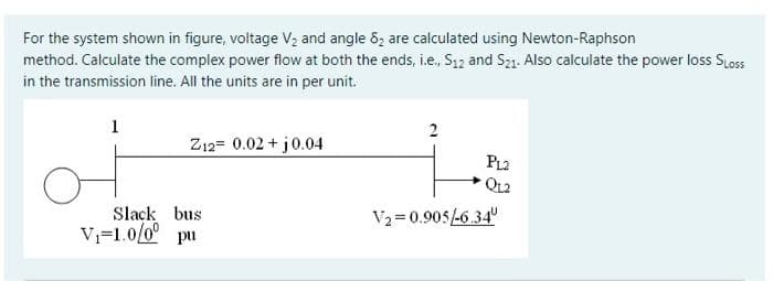
Step by step
Solved in 4 steps with 1 images
- Determine the bus admittance matrix (Ybus) for the three-phase power system shown in Figure 6.23 with input data given in Table 6.11 and partial results in Table 6.12. Assume a three-phase 100 MVA per unit base. TABLE 6.11 Bus input data for Problem 6.20 TABLE 6.12 Partially Completed Bus Admittance Matrix (Ybus) for Problem 6.30With generator conyention, where the current leaves the positive terminal of the circuit element, if P is positive then positive real power is delivered. (a) False (b) True3. Which one of the following method uses weak coupling between reactive power and voltage angle?. A. Newton - Raphson Method B. Decoupled Method C. Gauss-Seidal Method
- The annual load duration curve of a power supply system may be considered as straight line from 40 MW to 8 MW. The load factor of the system is ?At the end of the 8 km overhead line given in the figure below, there are two distribution transformers, one of which is 800kVA and the other is 1200kVA, operated with power coefficients of 0.6 and 0.8, respectively. The end-of-line voltage is 6kV. Find the required rated cross section and line head voltage so that the power loss on the line is less than %pk = 10.The figure below shows the one-line diagram of a simple three-bus power system withgeneration at bus 1. The voltage at bus 1 is V1 = 1.0∠0°per unit. The scheduledloads on buses 2 and 3 are marked on the diagram. Line impedances are marked inper unit on a 100 MVA base.(a) Using Gauss-Seidel method and initial estimates of ?2(0) = 1.0 + ?0, ?3(0) = 1.0 + ?0, determine V2and V3. Perform two iterations.(b) If after several iterations the bus voltages converge to?2 = 0.90 − ?0.10 pu?3 = 0.95 − ?0.05 pudetermine the line flows and line losses and the slack bus real and reactive power.
- The one line diagram of a three phase power system is as shown in Figure 7 Impedances are marked in per unit on a 100 MVA, 400 kV base The load at bus 2 is S2 15.93 MW - j 33.4 MVar, and at bus 3 is S3 77 MW + j 14 MVar It is required to hold the voltage at bus 3 at 400 kV Working in per unit, determine the voltage at buses 2 and 1Draw an impedance diagram for the electric power system shown in the figure attached, showing all impedances in per unit on a 100-MVA base. Choose 20kV as the voltage base for generator. The three-phase power and line-line ratings are given in the figure attached.Draw the per unit impedance diagram for the simple power system in the figure. Catalog of all elementsThe impedances in the information are listed below. The line's actual impedance value and the load'sThe MVA value is also included in this list. Assume a power base value of 100 MVA for all impedances.On the generator side, take the voltage base as 20-kV.
- Three zones of a single-phase circuit are identified in the figure with a generator voltage specification of 240 V. The zones are connected by the transformers T1 and T2, whose ratings are shown below.Using base values of 30 kVA and 240 volts in zone 1, draw the pu circuit and determine the pu impedance and pu source voltage. Then calculate the load current in pu and in amperes.*Round the final answer to four decimal places, polar form, and label it with the correct units.Figure shows the one-line diagram of a simple three-bus power system with generation at buses 1 and 3. The voltage at bus 1 is V1 is 1.025 at an angle of 0◦ per unit. Voltage magnitude at bus 3 is fixed at 1.03 pu with a real power generation of 300 MW. A load consisting of 400 MW and 200 MVAr is taken from bus 2. Line impedances are marked in per unit on a 100 MVA base. (a) Construct Ybus matrix for the system in Figure (b) Using Gauss-Seidel method and initial estimate of V2(0) = 1.0 + j0 and V3(0) = 1.03 + j0 and keeping |V3| = 1.03 pu, determine the phasor values of V2 and V3. Perform two iterations.Question 3. A three-phase impedance load balanced D a connected load in parallel with a balanced ? connected load made of bonding. D each arm for the load ?D = 6 + 6? and ? each arm for the connected load It is given as ?? = 2 + 2?. ? the connected load ?? = 1? is earthed through the neutral impedance. To this impedance load, the symmetrical component voltages ?0 = 10∠60°, ?1 = 100∠0° and ?2 = Unbalanced phase-to-earth voltages ??, ?? and ?? of 15∠200° volts were applied. a) Draw the zero, positive and negative sequence circuits. b) Find the complex powers imparted to each component circuit.