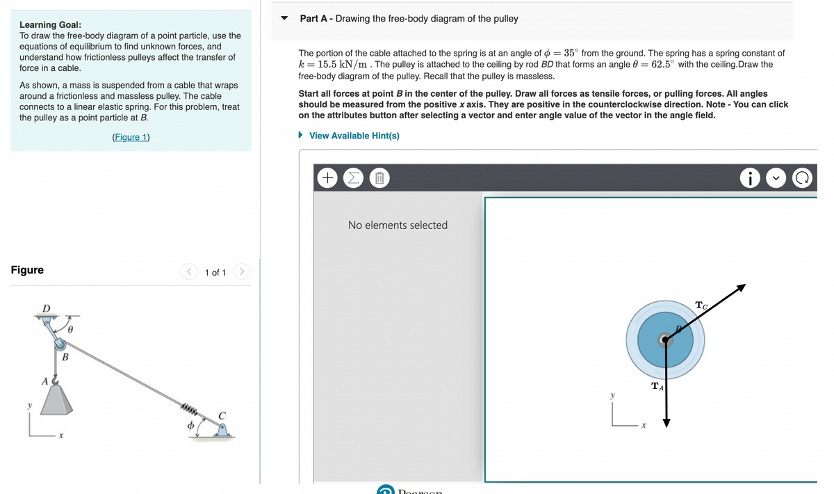
Learning Goal: To draw the free-body diagram of a point particle, use the equations of equilibrium to find unknown forces, and understand how frictionless pulleys affect the transfer of force in a cable. As shown, a mass is suspended from a cable that wraps around a frictionless and massless pulley. The cable connects to a linear elastic spring. For this problem, treat the pulley as a point particle at B. (Figure 1) Figure A 0 B b 1 of 1 > Part A - Drawing the free-body diagram of the pulley The portion of the cable attached to the spring is at an angle of = 35° from the ground. The spring has a spring constant of k = 15.5 kN/m. The pulley is attached to the ceiling by rod BD that forms an angle = 62.5° with the ceiling.Draw the free-body diagram of the pulley. Recall that the pulley is massless. Start all forces at point B in the center of the pulley. Draw all forces as tensile forces, or pulling forces. All angles should be measured from the positive x axis. They are positive in the counterclockwise direction. Note - You can click on the attributes button after selecting a vector and enter angle value of the vector in the angle field. ► View Available Hint(s) 0 No elements selected ΤΑ To (2
Learning Goal: To draw the free-body diagram of a point particle, use the equations of equilibrium to find unknown forces, and understand how frictionless pulleys affect the transfer of force in a cable. As shown, a mass is suspended from a cable that wraps around a frictionless and massless pulley. The cable connects to a linear elastic spring. For this problem, treat the pulley as a point particle at B. (Figure 1) Figure A 0 B b 1 of 1 > Part A - Drawing the free-body diagram of the pulley The portion of the cable attached to the spring is at an angle of = 35° from the ground. The spring has a spring constant of k = 15.5 kN/m. The pulley is attached to the ceiling by rod BD that forms an angle = 62.5° with the ceiling.Draw the free-body diagram of the pulley. Recall that the pulley is massless. Start all forces at point B in the center of the pulley. Draw all forces as tensile forces, or pulling forces. All angles should be measured from the positive x axis. They are positive in the counterclockwise direction. Note - You can click on the attributes button after selecting a vector and enter angle value of the vector in the angle field. ► View Available Hint(s) 0 No elements selected ΤΑ To (2

Principles of Heat Transfer (Activate Learning with these NEW titles from Engineering!)
8th Edition
ISBN:9781305387102
Author:Kreith, Frank; Manglik, Raj M.
Publisher:Kreith, Frank; Manglik, Raj M.
Chapter4: Numerical Analysis Of Heat Conduction
Section: Chapter Questions
Problem 4.52P

Related questions

Question
100%
I need help with Parts A and C on this question!
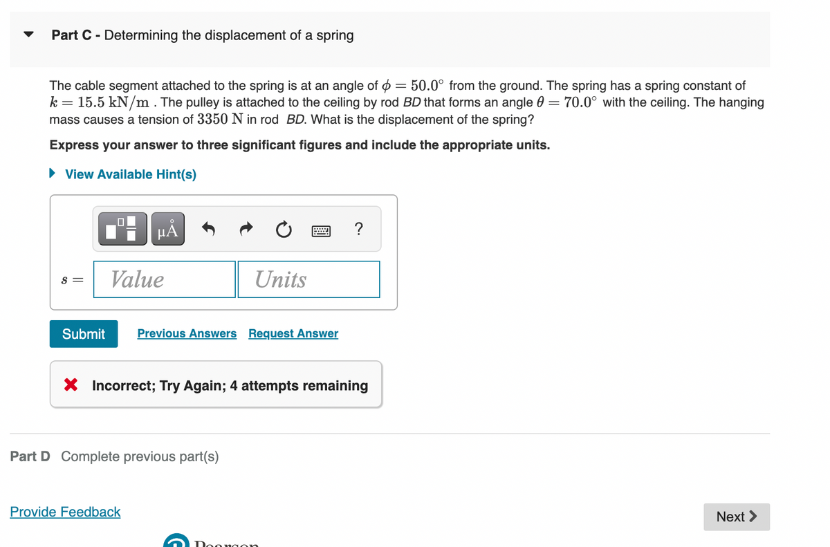
Transcribed Image Text:Part C - Determining the displacement of a spring
The cable segment attached to the spring is at an angle of = 50.0° from the ground. The spring has a spring constant of
k 15.5 kN/m. The pulley is attached to the ceiling by rod BD that forms an angle = 70.0° with the ceiling. The hanging
mass causes a tension of 3350 N in rod BD. What is the displacement of the spring?
=
Express your answer to three significant figures and include the appropriate units.
View Available Hint(s)
S =
µA
Value
Units
Submit Previous Answers Request Answer
Part D Complete previous part(s)
Provide Feedback
*****
X Incorrect; Try Again; 4 attempts remaining
Doongon
?
Next >
Transcribed Image Text:Learning Goal:
To draw the free-body diagram of a point particle, use the
equations of equilibrium to find unknown forces, and
understand how frictionless pulleys affect the transfer of
force in a cable.
As shown, a mass is suspended from a cable that wraps
around a frictionless and massless pulley. The cable
connects to a linear elastic spring. For this problem, treat
the pulley as a point particle at B.
(Figure 1)
Figure
A
B
1 of 1
Part A - Drawing the free-body diagram of the pulley
The portion of the cable attached to the spring is at an angle of = 35° from the ground. The spring has a spring constant of
k = 15.5 kN/m. The pulley is attached to the ceiling by rod BD that forms an angle = 62.5° with the ceiling.Draw the
free-body diagram of the pulley. Recall that the pulley is massless.
Start all forces at point B in the center of the pulley. Draw all forces as tensile forces, or pulling forces. All angles
should be measured from the positive x axis. They are positive in the counterclockwise direction. Note - You can click
on the attributes button after selecting a vector and enter angle value of the vector in the angle field.
► View Available Hint(s)
+ Σ O
No elements selected
Doongon
X
ΤΑ
To
Expert Solution
This question has been solved!
Explore an expertly crafted, step-by-step solution for a thorough understanding of key concepts.

This is a popular solution!

Trending now
This is a popular solution!

Step by step
Solved in 2 steps with 2 images

Knowledge Booster


Learn more about
Need a deep-dive on the concept behind this application? Look no further. Learn more about this topic, mechanical-engineering and related others by exploring similar questions and additional content below.Recommended textbooks for you
Principles of Heat Transfer (Activate Learning wi…
Mechanical Engineering
ISBN:
9781305387102
Author:
Kreith, Frank; Manglik, Raj M.
Publisher:
Cengage Learning
Principles of Heat Transfer (Activate Learning wi…
Mechanical Engineering
ISBN:
9781305387102
Author:
Kreith, Frank; Manglik, Raj M.
Publisher:
Cengage Learning