m1, VI 0 m₂V₁cos e-m₂V2 - m3V3 + F₁ System boundary = FIGURE 7.27 A jet impinging on a surface not perpendicular to it. We solve in the r-s coordinate system, instead of the x-y system. L From the assumption of frictionless flow, we can see that F, 0, that the absolute magnitudes of V₁, V2, and V3 are the same, but that V3 is in the -s direction, so that it is equal to -V₁. Making these substitutions and dividing by V₁ we find 0 m₁ cos 0 m₂ + m3 (7.65) (a) Using the material balance to eliminate m3 show the equation for m2/m₁. (b) Show the equation for the force exerted on the wall in the r direction.
m1, VI 0 m₂V₁cos e-m₂V2 - m3V3 + F₁ System boundary = FIGURE 7.27 A jet impinging on a surface not perpendicular to it. We solve in the r-s coordinate system, instead of the x-y system. L From the assumption of frictionless flow, we can see that F, 0, that the absolute magnitudes of V₁, V2, and V3 are the same, but that V3 is in the -s direction, so that it is equal to -V₁. Making these substitutions and dividing by V₁ we find 0 m₁ cos 0 m₂ + m3 (7.65) (a) Using the material balance to eliminate m3 show the equation for m2/m₁. (b) Show the equation for the force exerted on the wall in the r direction.

Elements Of Electromagnetics
7th Edition
ISBN:9780190698614
Author:Sadiku, Matthew N. O.
Publisher:Sadiku, Matthew N. O.
ChapterMA: Math Assessment
Section: Chapter Questions
Problem 1.1MA

Related questions

Question
Please answer!!
Transcribed Image Text:7.7.
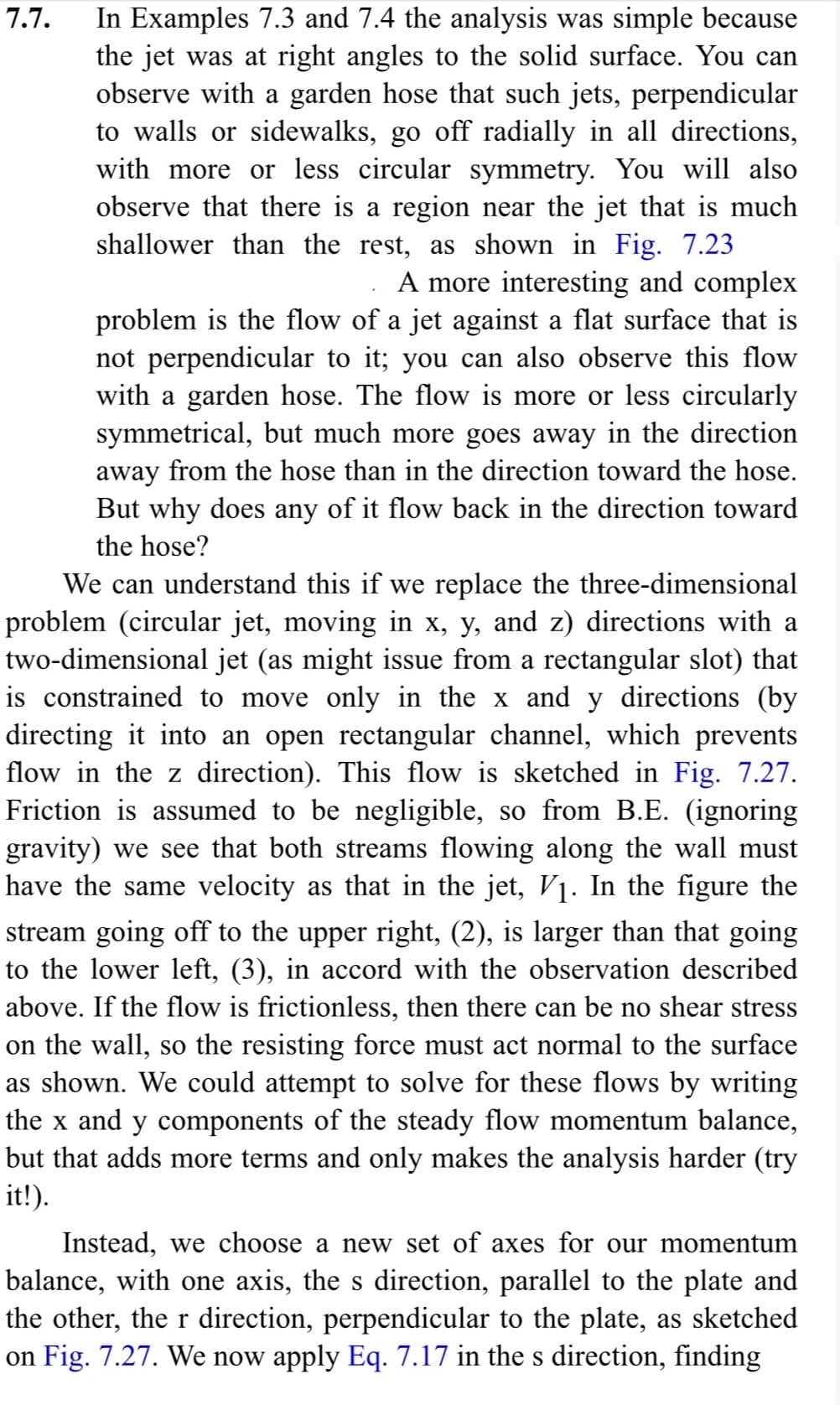
In Examples 7.3 and 7.4 the analysis was simple because
the jet was at right angles to the solid surface. You can
observe with a garden hose that such jets, perpendicular
to walls or sidewalks, go off radially in all directions,
with more or less circular symmetry. You will also
observe that there is a region near the jet that is much
shallower than the rest, as shown in Fig. 7.23
A more interesting and complex
problem is the flow of a jet against a flat surface that is
not perpendicular to it; you can also observe this flow
with a garden hose. The flow is more or less circularly
symmetrical, but much more goes away in the direction
away from the hose than in the direction toward the hose.
But why does any of it flow back in the direction toward
the hose?
We can understand this if we replace the three-dimensional
problem (circular jet, moving in x, y, and z) directions with a
two-dimensional jet (as might issue from a rectangular slot) that
is constrained to move only in the x and y directions (by
directing it into an open rectangular channel, which prevents
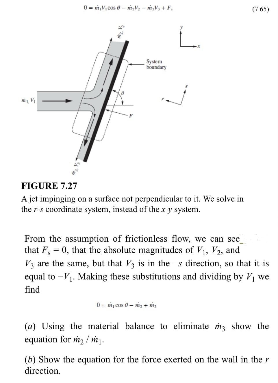
flow in the z direction). This flow is sketched in Fig. 7.27.
Friction is assumed to be negligible, so from B.E. (ignoring
gravity) we see that both streams flowing along the wall must
have the same velocity as that in the jet, V₁. In the figure the
stream going off to the upper right, (2), is larger than that going
to the lower left, (3), in accord with the observation described
above. If the flow is frictionless, then there can be no shear stress
on the wall, so the resisting force must act normal to the surface
as shown. We could attempt to solve for these flows by writing
the x and y components of the steady flow momentum balance,
but that adds more terms and only makes the analysis harder (try
it!).
Instead, we choose a new set of axes for our momentum
balance, with one axis, the s direction, parallel to the plate and
the other, the r direction, perpendicular to the plate, as sketched
on Fig. 7.27. We now apply Eq. 7.17 in the s direction, finding
Transcribed Image Text:m1, V₁
0 m₂V₁ cos 0 - m₂V₂ - m3V3 + F₁
m₂, V₂
System
boundary
FIGURE 7.27
A jet impinging on a surface not perpendicular to it. We solve in
the r-s coordinate system, instead of the x-y system.
(7.65)
From the assumption of frictionless flow, we can see
that F = 0, that the absolute magnitudes of V₁, V2, and
V3 are the same, but that V3 is in the -s direction, so that it is
equal to - V₁. Making these substitutions and dividing by V₁ we
find
0 m₁ cos 0 m₂ + m3
(a) Using the material balance to eliminate m3 show the
equation for m2 /m₁.
(b) Show the equation for the force exerted on the wall in the r
direction.
Expert Solution
This question has been solved!
Explore an expertly crafted, step-by-step solution for a thorough understanding of key concepts.

This is a popular solution!

Trending now
This is a popular solution!

Step by step
Solved in 4 steps with 4 images

Knowledge Booster


Learn more about
Need a deep-dive on the concept behind this application? Look no further. Learn more about this topic, mechanical-engineering and related others by exploring similar questions and additional content below.Recommended textbooks for you
Elements Of Electromagnetics
Mechanical Engineering
ISBN:
9780190698614
Author:
Sadiku, Matthew N. O.
Publisher:
Oxford University Press

Mechanics of Materials (10th Edition)
Mechanical Engineering
ISBN:
9780134319650
Author:
Russell C. Hibbeler
Publisher:
PEARSON

Thermodynamics: An Engineering Approach
Mechanical Engineering
ISBN:
9781259822674
Author:
Yunus A. Cengel Dr., Michael A. Boles
Publisher:
McGraw-Hill Education
Elements Of Electromagnetics
Mechanical Engineering
ISBN:
9780190698614
Author:
Sadiku, Matthew N. O.
Publisher:
Oxford University Press
Mechanics of Materials (10th Edition)
Mechanical Engineering
ISBN:
9780134319650
Author:
Russell C. Hibbeler
Publisher:
PEARSON
Thermodynamics: An Engineering Approach
Mechanical Engineering
ISBN:
9781259822674
Author:
Yunus A. Cengel Dr., Michael A. Boles
Publisher:
McGraw-Hill Education

Control Systems Engineering
Mechanical Engineering
ISBN:
9781118170519
Author:
Norman S. Nise
Publisher:
WILEY

Mechanics of Materials (MindTap Course List)
Mechanical Engineering
ISBN:
9781337093347
Author:
Barry J. Goodno, James M. Gere
Publisher:
Cengage Learning

Engineering Mechanics: Statics
Mechanical Engineering
ISBN:
9781118807330
Author:
James L. Meriam, L. G. Kraige, J. N. Bolton
Publisher:
WILEY