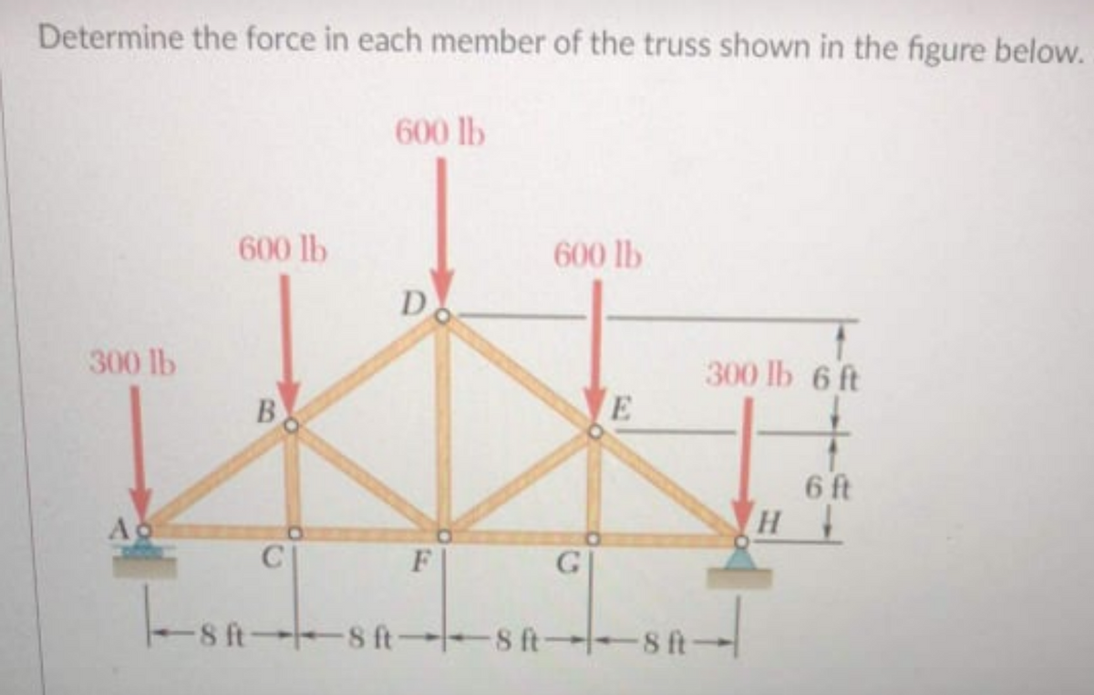
Determine the force in each member of the truss shown in the figure below. 600 lb 600 lb 600 lb D 300 lb 300 lb 6 ft B E 6 ft Ao H C| F G -8 t- -8 ft -8 ft -8 ft- 8 ft-


Q: Item 4. Two cars are on the bridge as shown in the figure. Find the support force at position A and…
A:
Q: The following truss is loaded as can be seen in the image. Find the forces in members DF, DE, and…
A:
Q: O The truss is subjected to the loading condition as shown in the Figure Q4.1. Identify and…
A:
Q: The simple truss is loaded by a system of forces as shown in the figure. The truss is supported by a…
A:
Q: The simple truss is loaded by a system of forces as shown in the figure. The truss is supported by a…
A:
Q: Determine the horizontal and vertical components of force which the pin at B exerts on member BC of…
A: The free body diagram of the beam is as follows:
Q: The reactions at the rigid supports at A and B for the bar loaded as shown in the figure are…
A: Given : P = 10 KN To find : reactions at the rigid supports at A and B
Q: The light boom AB is attached to a vertical wall by a ball and socket joint at A and supported by…
A:
Q: 1) Consider the frame below. 4 kN/m 20 mm D 60 mm B E 20 mm D. 50 mm |-1.5 m --1.5 m -† - 3 m 5m 3 m
A:
Q: 4) Use the method of members to find the true magnitude and direction of the forces in the members…
A:
Q: 70 in - 36 in - y 20 in 3300 lb
A: 1) As given in question rear wheels are locked and front are free to turn so we can consider front…
Q: Consider the figure shown below. Determine the force on each members of the truss. 100 kN 100 kN B D…
A:
Q: Q. 3 Determine the force in each member by using method of joint in given figure 3. State whether…
A: Given , A truss member .
Q: Determine the axial force in the bars 1 & 4 of the tower shown in the figure due to a horizontal…
A:
Q: For the truss in the figure below, if P = 7 kN, what is the force in member DC? -3 m-3 m-3 m- F E VP…
A: Given data P=7 kN
Q: Compute the force in each member of the loaded cantilever truss as shown in the figure below. B 5 m…
A:
Q: The truss is subjected to the system of forces as shown in the following figure. The truss is…
A: Take moment about the point E = 0
Q: The truss is subjected to the system of forces as shown in the following figure. The truss is…
A:
Q: For the given loads w = 28 KN/m and M=70 KN.m is supported as shown by a roller at D and a hinge at…
A: UDL is referred to uniformly distributed load (magnitude of load remains constant over a span of…
Q: Q.2) For the system and load shown in figure, Determine the reaction forces of bearing at A and B,…
A: The coordinates of points C and D from the figure are, Let the tension in the cable CD be T The…
Q: The truss is subjected to the system of forces as shown in the following figure. The truss is…
A: Given data :- At A = 6 KN At E = 8 KN Find :- The force in Member AE = ?
Q: Determine the force in members ac,be,ce,ei & gh of truss shown in figure h Ap 4 4m 4m 4m 4m + + 6000…
A:
Q: 20 kg is supported by two inclined planes, as shown. Sketch
A: given:mass of cylinder m=120kg
Q: 4) Use the method of members to find the true magnitude and direction of the forces in the members…
A:
Q: The truss is subjected to the system of forces as shown in the following figure. The truss is…
A:
Q: The simple truss is loaded by a system of forces as shown in the figure. The truss is supported by a…
A: Given data: The load P1 is P1 = 40 kN. The load P2 is P2 = 20 kN. The distance between FE is x =…
Q: · 400 mm- 1. A block with a mass of 150-kg is supported by a cable which passes over a 150-mm…
A: Given data: - The mass of the block is m = 150 kg. The distance between AB is h = 450 mm. The…
Q: The simple truss is loaded by a system of forces as shown in the figure. The truss is supported by a…
A:
Q: The simple truss is loaded by a system of forces as shown in the figure. The truss is supported by a…
A:
Q: 2m B 3m 4m 30° 52 KN
A:
Q: In the figure shown, the frame is supported using a hinge in point A and a roller in point B. The…
A:
Q: The light boom AB is attached to a vertical wall by a ball and socket joint at A and supported by…
A: Given that The force P→ is 19i^-10j^ KNThe coordinates from the figure are:A 2,0,-3; B (0,6,0); C…
Q: Need answer please
A:
Q: The three-hinged tied arch is subjected to the loading shown in the figure. Determine the force in…
A:
Q: 4. (a) Determine the force in each member of the truss shown in Figure 4a and state if the members…
A:
Q: The truss is subjected to the system of forces as shown in the following figure. The truss is…
A:
Q: The simple truss is loaded by a system of forces as shown in the figure. The truss is supported by a…
A:
Q: . From the system shown in the figure, obtain the forces and the average axial stres on each bar AB,…
A:
Q: The truss shown in the figure is applied with force P = 5 KN. Which of following nearly gives the…
A:
Q: The truss shown in the figure is pin supported at A and witha roller at G. Determine the magnitude…
A:
Q: The simple truss is loaded by a system of forces as shown in the figure. The truss is supported by a…
A:
Q: 3: In Fig. 2, Find the Force in members DC, EC, EF Using Method of Sections and in Members AE & BG…
A: Given data as per the question Force applied at F =6 KN Force applied at G =2KN RA+RB=3+6+2=11…
Q: b) For the truss in the figure below, determine the zero-force members and give a short explanation…
A:
Q: The simple truss is loaded by a system of forces as shown in the figure. The truss is supported by a…
A:
Q: Q. 3 Determine the force in each member by using method of joint in given figure 3. State whether…
A: Concept of method of joints are used to solve the problem.
Q: Determine the force in member EI of the truss which serves to support the deck of a bridge.…
A: FBD of the given problem:
Q: The simple truss is loaded by a system of forces as shown in the figure. The truss is supported by a…
A: Given data: The magnitude of the force P acting on the truss is P = 800 lb.
Q: The truss is subjected to the system of forces as shown in the following figure. The truss is…
A: The free body diagram of the truss is given below,
Q: From the figure, the load at G is 12 kN: To determine: a) Piston force JL b) Pin force E and M c)…
A: Draw FBD of GEM and calculate pin forces at E and M:
Q: The truss is subjected to the system of forces as shown in the following figure. The truss is…
A: The free body diagram at the point E is as follows: Calculate the vertical force at the joint E is…
Q: Situation 9 - The 10-kN and 40-kN forces 40 kN are applied to the pins at B and C, respectively.…
A:
Q: For the loaded truss shown in the figure below and using the method of sections, 1) Determine the…
A: Given: Load, P = 1.7 kN To analyze the truss by method of sections, we assume a section X-X cutting…
Q: The truss is subjected to the system of forces as shown in the following figure. The truss is…
A: Given data The truss is subjected to the system of forces as shown in the following figure. The…

Step by step
Solved in 2 steps with 6 images

- A long re Lai nine: wall is braced by wood shores set at an angle of 30° and supported by concrete thrust blocks, as shown in the first part of the figure. The shores are evenly spaced at 3 m apart. For analysis purposes, the wall and shores are idealized as shown in the second part of the figure. Note that the base of the wall and both ends of the shores are assumed to be pinned. The pressure of the soil against the wall is assumed to be triangularly distributed, and the resultant force acting on a 3-meter length of the walls is F = 190 kN. If each shore has a 150 mm X 150 mm square cross section, what is the compressive stressThe figure shows the FBD of a portion of the space truss shown in Fig. P5.25. Use this FBD to find the force in member BD.A lifeboat hangs from two ship's davits. as shown in the figure. A pin of diameter d = 0.80 in. passes through each davit and supports two pulleys. are on each side of the davit. Cables attached to the lifeboat pass over the pulleys and wind around winches that raise and lower the lifeboat. The lower parts of the cables are vertical and the upper parts make an angle a =15° with the horizontal. The allowable tensile force in each cable is 1800 lb, and the allowable shear stress in the pins is 4000 psi. If the lifeboat weighs 1500 lb, what is the maximum weight that can be carried in the lifeboat?
- A large precast concrete panel for a warehouse is raised using two sets of cables at two lift lines, as shown in the figure part a. Cable 1 has a length L1 = 22 Ft, cable 2 has a length L2= 10 ft, and the distance along the panel between lift points Band D is d = 14 ft (see figure part b). The total weight of the panel is W = 85 kips. Assuming the cable lift Forces F at each lift line are about equal, use the simplified model of one half of the panel in figure part b to perform your analysis for the lift position shown. Find the required cross-sectional area AC of the cable if its breaking stress is 91 ksi and a factor of safety of 4 with respect to failure is desired.A plane truss has a pin support at F and a roller support at D (see figure). (a) Find reactions at both supports (b) Find the axial force in truss member FE.Continuous cable A DB runs over a small friction less pulley al D to support beam OABC, which is part of an entrance canopy for a building (see figure}. The canopy segment has a weight W = 1700 lb that acts as a concentrated load in the middle of segment AB. (a) What is the maximum permissible value of load P at C if the allowable force in the cable is 4200 lb? (b) If P = 2300 lb, what is the required diameter of pins A, B, and D? Assume that the pins are in double shear and the allowable shear stress in the pins is 10 ksi.
- Repeat Problem 11.2-3 assuming that R= 10 kN · m/rad and L = 2 m.Consider the plane truss with a pin support at joint 3 and a crtica1 roller support at joint 5 (see figure). (a) Find reactions at support joints 3 and 5. (b) Find axial forces in truss members 11 and 13.A plane Frame is restrained at joints A and D, as shown in the figure. Members AB and BCD are pin connected at B. A triangularly distributed lateral load with peak intensity of SO N/m acts on CD. An inclined concentrated force of 200 N acts at the mid-span of BC. (a) Find reactions at supports A and D. (b) Find resultant forces in the pins at B and C.
- A plane truss has joint loads P, 2P, and 3P at joints D. C, and B. respectively (see figure) where load variable P — 5200 lb. All members have two end plates (see figure For Prob. 1.8-2) that are pin-connected to gusset plates. Each end plate has a thickness/ — 0.6.2.5 in., and all gusset plates have a thickness tg= 1.125 in. IT the allowable shear stress in each pin is 12,000 psi and the allowable bearing stress in each pin is 18.000 psi, what is the minimum required diameter dminof the pins used at either end of member BE1Two steel wines support a moveable overhead camera weighing W = 28 lb (see figure part a) used For close-up to viewing of field action at sporting, events. At some instant, wire I is at an angle a = 22° to the horizontal and wire 2 is at angle fi = 40°. Wires I and 2 have diameters of 30and 35 mils, respectively. (Wire diameters are often expressed in mils; one mil equals 0.001 in.) (a) Determine the tensile stresses s and s2 in the two wires. (b) If the stresses in wires 1 and 2 must be the same, what is the required diameter of wire 1 ? (c) To stabilize the camera for windy outdoor conditions, a third wire is added (see figure part b). Assume the three wires meet at a common point coordinates (0, 0. 0) above the camera at the instant shown in figure part b. Wire I is attached to a support at coordinates (75 ft, 48 ft, 70 Ft). Wire 2 is supported at (-70 ft. 55 ft, 80 Ft). Wire 3 is supported at (-10 ft. -85 Ft, 75 ft). Assume that all three wires have a diameter of 30 mils. Find the tensile stresses in all three wiresTRUSS PROBLEM please show all working out answers: F1-2 = -43 kN (compression)F1-3 = -25 kN (compression)F2-3 = +22 kN (tension)
