In the figure shown, the frame is supported using a hinge in point A and a roller in point B. The members ACE and BCD are connected by a pin at C and by the link DE. Determine the force in link DE and CD. 160 mm B 480 N 60 mm 80 mm |E -150 mm 60 mm 100 mm
In the figure shown, the frame is supported using a hinge in point A and a roller in point B. The members ACE and BCD are connected by a pin at C and by the link DE. Determine the force in link DE and CD. 160 mm B 480 N 60 mm 80 mm |E -150 mm 60 mm 100 mm

International Edition---engineering Mechanics: Statics, 4th Edition
4th Edition
ISBN:9781305501607
Author:Andrew Pytel And Jaan Kiusalaas
Publisher:Andrew Pytel And Jaan Kiusalaas
Chapter6: Beams And Cables
Section: Chapter Questions
Problem 6.15P: The structure is supported by a pin at C and a cable attached to A. The cable runs over the small...

Related questions

Question
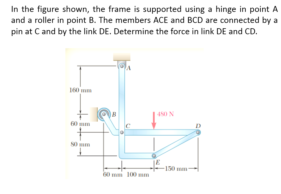
Transcribed Image Text:In the figure shown, the frame is supported using a hinge in point A
and a roller in point B. The members ACE and BCD are connected by a
pin at C and by the link DE. Determine the force in link DE and CD.
A
160 mm
480 N
60 mm
C
D
80 mm
|E
-150 mm
60 mm 100 mm
Expert Solution
This question has been solved!
Explore an expertly crafted, step-by-step solution for a thorough understanding of key concepts.

This is a popular solution!

Trending now
This is a popular solution!

Step by step
Solved in 2 steps with 3 images

Knowledge Booster


Learn more about
Need a deep-dive on the concept behind this application? Look no further. Learn more about this topic, mechanical-engineering and related others by exploring similar questions and additional content below.Recommended textbooks for you
International Edition---engineering Mechanics: St…
Mechanical Engineering
ISBN:
9781305501607
Author:
Andrew Pytel And Jaan Kiusalaas
Publisher:
CENGAGE L
International Edition---engineering Mechanics: St…
Mechanical Engineering
ISBN:
9781305501607
Author:
Andrew Pytel And Jaan Kiusalaas
Publisher:
CENGAGE L