A simply supported beam (i.e., with a pin support at point A and a roller support at point D) is subjected to the external loadings shown in the figure. The cross- soction is shown to the right of the beam. 10 IN 10 KN mm 10mm Determine the shear stress developed in the cross-section n-n at point E on the web, 2m S0mm
A simply supported beam (i.e., with a pin support at point A and a roller support at point D) is subjected to the external loadings shown in the figure. The cross- soction is shown to the right of the beam. 10 IN 10 KN mm 10mm Determine the shear stress developed in the cross-section n-n at point E on the web, 2m S0mm

Mechanics of Materials (MindTap Course List)
9th Edition
ISBN:9781337093347
Author:Barry J. Goodno, James M. Gere
Publisher:Barry J. Goodno, James M. Gere
Chapter6: Stresses In Beams (advanced Topics)
Section: Chapter Questions
Problem 6.10.1P: Determine the shape factor f for a cross section in the shape of a double trapezoid having the...

Related questions
Question
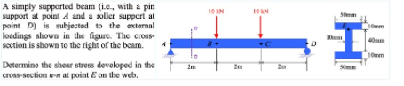
Transcribed Image Text:A simply supported beam (i.e., with a pin
support at point A and a roller support at
point D) is subjected to the external
loadings shown in the figure. The cross-
soction is shown to the right of the beam.
10 IN
10 KN
mm
10mm
Determine the shear stress developed in the
cross-section n-n at point E on the web,
2m
S0mm
Expert Solution
This question has been solved!
Explore an expertly crafted, step-by-step solution for a thorough understanding of key concepts.

Step by step
Solved in 2 steps with 2 images

Recommended textbooks for you
Mechanics of Materials (MindTap Course List)
Mechanical Engineering
ISBN:
9781337093347
Author:
Barry J. Goodno, James M. Gere
Publisher:
Cengage Learning
Mechanics of Materials (MindTap Course List)
Mechanical Engineering
ISBN:
9781337093347
Author:
Barry J. Goodno, James M. Gere
Publisher:
Cengage Learning