Print Reading for Industry 430 Class Name Date Industry Print Exercise 22-1 Refer to the print PR 22-1 and answer the questions below. 1. What is the total number of parts required to make the welded assembly? 2. How many welding symbols are on the print? 3. How many different types of welds are specified on the print and what are they? 4. For the weld between parts TP1 and TP2, what does the 3 mean? 5. What standard should be used to interpret the weld symbols on this print? 6. As indicated by the welding symbols, are the welds to be made on the near side, far side, or both sides? 7. What note is found in the tail of the welding symbol? 8. Are any field welds indicated? Review questions based on previous units: 9. What is the hole diameter for the small hole located on part AAA316FTP2? 10. What is the largest diameter on this assembly? 11. What geometric tolerancing controls are used on this print? 12. What is the name of this part? 13. What is the smoothest surface finish specified on this print? 14. In the local note for the holes marked M6, what does B.C. stand for? 15. As shown in the sectional side view, what is the total depth of this welded part? Copyright Goodheart-Willcox Co., Inc. Unit 22 Welding Prints 4 AAA316FTP DWG 228 31 +0,3 43 22 TZ blow E0OO Ø125H7 bi lodm Ø140 Su 9.5 e 0 o PR 22-1. Bracket Mounting. Print supplied by United Technologies Otis. Copyright Goodheart-Willcox Co., Inc. 120-400 t0,3 50-120 3-6 6-30 ANGLE (shor ler side length) O,5-10 10-50 ALL DIMENSIONS METRIC 30-120 120-315 O.5-3 A OLERANCE 3-6 6-30 30 120 120 315 315 10000 1000-2000 RAD. /CHAN 0.5-3 40.2 0.5 +8 TOLERANCE + 0,8 t0, +0.8 1,2 +3 TOLERANCE 0.2 + 2 24 NOTES: TOLERANCE 6,3 ALL OVER EXCEPT AS NOTED. 2. BREAK ALL SHARP CORNERS RO, I15 FIT 125H7 0.040 0 3. WELD SYMBOLS IN ACCORDANCE WI TH ISO 2553. 0.033 93061 DATE PART ASSEMBLY OF AAA316FTPI 01-60 AAA316FTP2 AAA316FTP3 B AAA316FTP4 AAA316FTPI, (4)AAA316FTP2, AAA316FTP3 54 15 34 .0.9 20 (4)M5 x 10 DEEP- EQUALLY SPACED 06 (4)M5 THRU- ON 105 B.C EQUALLY SPACED 9 AAA316FTPI 9 1 O0.05 C (2)M6 THRU- ON A 208 B.C TYP ICAL 4c AAA316FTP3 (6)7 THRU- ON 208 B.C EQUALLY SPACED 3 4,15 TYPICAL SEE NOTE 3 4512 6,35 I x 45 CHAMFER Q.025 B A-A AAA316FTP2- CHANGES AAA316FTP SINL BRACKET, MOUNTING DWG OLIVEREO T0 OTNERS ON THE EIPRLSS CONDITIO THA OTIS ENGINEERING CENTER FARMINGTON PART CT ww eti10nn AN SANDIN AAA21 430E 0RAN W.KING ORIGINAL DATE NO 01sn is81 UNITED 2 T APPO J. L.H. ORDER PCAF 2 721 01-60 SHEETS 3 OTIS SHEET MICROFILM 24:1 CAD GENERATED
Print Reading for Industry 430 Class Name Date Industry Print Exercise 22-1 Refer to the print PR 22-1 and answer the questions below. 1. What is the total number of parts required to make the welded assembly? 2. How many welding symbols are on the print? 3. How many different types of welds are specified on the print and what are they? 4. For the weld between parts TP1 and TP2, what does the 3 mean? 5. What standard should be used to interpret the weld symbols on this print? 6. As indicated by the welding symbols, are the welds to be made on the near side, far side, or both sides? 7. What note is found in the tail of the welding symbol? 8. Are any field welds indicated? Review questions based on previous units: 9. What is the hole diameter for the small hole located on part AAA316FTP2? 10. What is the largest diameter on this assembly? 11. What geometric tolerancing controls are used on this print? 12. What is the name of this part? 13. What is the smoothest surface finish specified on this print? 14. In the local note for the holes marked M6, what does B.C. stand for? 15. As shown in the sectional side view, what is the total depth of this welded part? Copyright Goodheart-Willcox Co., Inc. Unit 22 Welding Prints 4 AAA316FTP DWG 228 31 +0,3 43 22 TZ blow E0OO Ø125H7 bi lodm Ø140 Su 9.5 e 0 o PR 22-1. Bracket Mounting. Print supplied by United Technologies Otis. Copyright Goodheart-Willcox Co., Inc. 120-400 t0,3 50-120 3-6 6-30 ANGLE (shor ler side length) O,5-10 10-50 ALL DIMENSIONS METRIC 30-120 120-315 O.5-3 A OLERANCE 3-6 6-30 30 120 120 315 315 10000 1000-2000 RAD. /CHAN 0.5-3 40.2 0.5 +8 TOLERANCE + 0,8 t0, +0.8 1,2 +3 TOLERANCE 0.2 + 2 24 NOTES: TOLERANCE 6,3 ALL OVER EXCEPT AS NOTED. 2. BREAK ALL SHARP CORNERS RO, I15 FIT 125H7 0.040 0 3. WELD SYMBOLS IN ACCORDANCE WI TH ISO 2553. 0.033 93061 DATE PART ASSEMBLY OF AAA316FTPI 01-60 AAA316FTP2 AAA316FTP3 B AAA316FTP4 AAA316FTPI, (4)AAA316FTP2, AAA316FTP3 54 15 34 .0.9 20 (4)M5 x 10 DEEP- EQUALLY SPACED 06 (4)M5 THRU- ON 105 B.C EQUALLY SPACED 9 AAA316FTPI 9 1 O0.05 C (2)M6 THRU- ON A 208 B.C TYP ICAL 4c AAA316FTP3 (6)7 THRU- ON 208 B.C EQUALLY SPACED 3 4,15 TYPICAL SEE NOTE 3 4512 6,35 I x 45 CHAMFER Q.025 B A-A AAA316FTP2- CHANGES AAA316FTP SINL BRACKET, MOUNTING DWG OLIVEREO T0 OTNERS ON THE EIPRLSS CONDITIO THA OTIS ENGINEERING CENTER FARMINGTON PART CT ww eti10nn AN SANDIN AAA21 430E 0RAN W.KING ORIGINAL DATE NO 01sn is81 UNITED 2 T APPO J. L.H. ORDER PCAF 2 721 01-60 SHEETS 3 OTIS SHEET MICROFILM 24:1 CAD GENERATED

Welding: Principles and Applications (MindTap Course List)
8th Edition
ISBN:9781305494695
Author:Larry Jeffus
Publisher:Larry Jeffus
Chapter28: Filler Metal Selection
Section: Chapter Questions
Problem 25R: Referring to Table 28-5, what stainless steel filler metal would be selected for welding a. 304L...

Related questions

Question
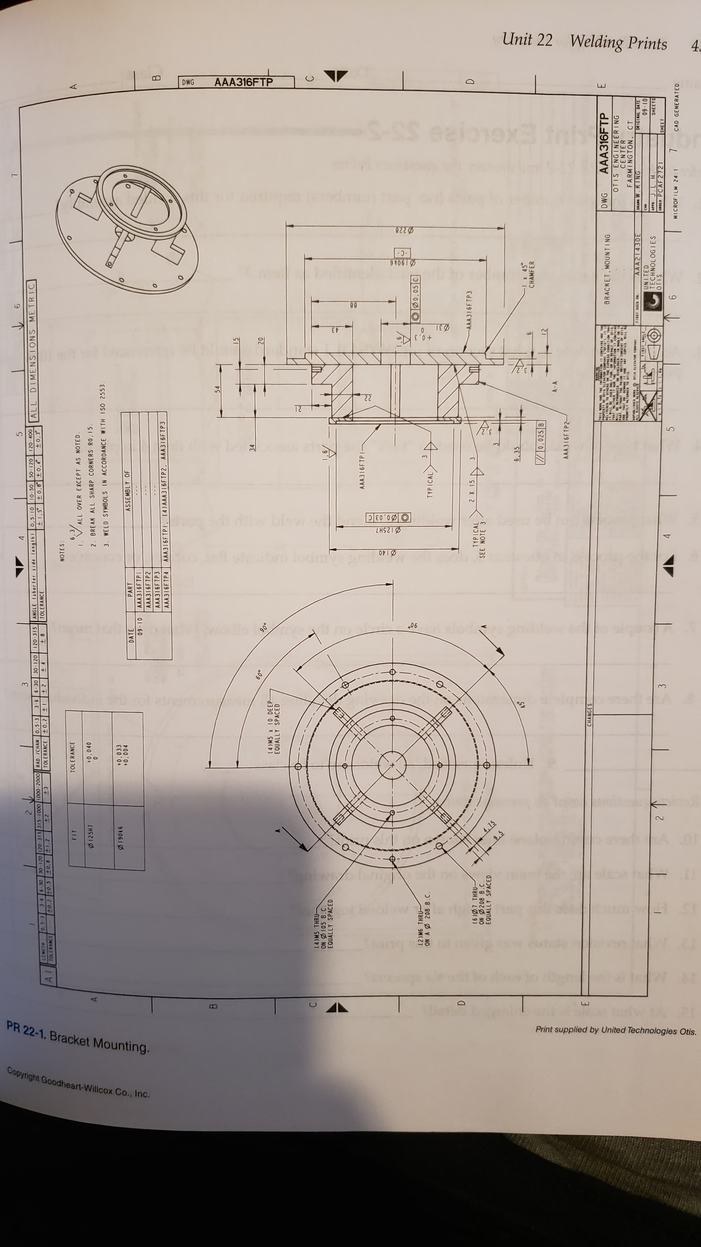
I need answers to parts 10, 11, and 12, pertaining to the print provided.

Transcribed Image Text:Print Reading for Industry
430
Class
Name
Date
Industry Print Exercise 22-1
Refer to the print PR 22-1 and answer the questions below.
1. What is the total number of parts required to make the welded assembly?
2. How many welding symbols are on the print?
3. How many different types of welds are specified on the print and what are they?
4. For the weld between parts TP1 and TP2, what does the 3 mean?
5. What standard should be used to interpret the weld symbols on this print?
6. As indicated by the welding symbols, are the welds to be made on the near side, far side, or both sides?
7. What note is found in the tail of the welding symbol?
8. Are any field welds indicated?
Review questions based on previous units:
9. What is the hole diameter for the small hole located on part AAA316FTP2?
10. What is the largest diameter on this assembly?
11. What geometric tolerancing controls are used on this print?
12. What is the name of this part?
13. What is the smoothest surface finish specified on this print?
14. In the local note for the holes marked M6, what does B.C. stand for?
15. As shown in the sectional side view, what is the total depth of this welded part?
Copyright Goodheart-Willcox Co., Inc.
Transcribed Image Text:Unit 22
Welding Prints
4
AAA316FTP
DWG
228
31
+0,3
43
22
TZ
blow
E0OO
Ø125H7
bi lodm
Ø140
Su
9.5
e
0 o
PR 22-1. Bracket Mounting.
Print supplied by United Technologies Otis.
Copyright Goodheart-Willcox Co., Inc.
120-400
t0,3
50-120
3-6 6-30
ANGLE (shor ler side length) O,5-10 10-50
ALL DIMENSIONS METRIC
30-120
120-315
O.5-3
A OLERANCE
3-6 6-30 30 120 120 315 315 10000 1000-2000 RAD. /CHAN 0.5-3
40.2 0.5
+8
TOLERANCE
+ 0,8 t0,
+0.8 1,2
+3
TOLERANCE 0.2
+ 2
24
NOTES:
TOLERANCE
6,3
ALL OVER EXCEPT AS NOTED.
2. BREAK ALL SHARP CORNERS RO, I15
FIT
125H7
0.040
0
3. WELD SYMBOLS IN ACCORDANCE WI TH ISO 2553.
0.033
93061
DATE
PART
ASSEMBLY OF
AAA316FTPI
01-60
AAA316FTP2
AAA316FTP3
B
AAA316FTP4
AAA316FTPI, (4)AAA316FTP2, AAA316FTP3
54
15
34
.0.9
20
(4)M5 x 10 DEEP-
EQUALLY SPACED
06
(4)M5 THRU-
ON 105 B.C
EQUALLY SPACED
9
AAA316FTPI
9 1
O0.05 C
(2)M6 THRU-
ON A 208 B.C
TYP ICAL
4c
AAA316FTP3
(6)7 THRU-
ON 208 B.C
EQUALLY SPACED
3
4,15
TYPICAL
SEE NOTE 3
4512
6,35
I x 45
CHAMFER
Q.025 B
A-A
AAA316FTP2-
CHANGES
AAA316FTP
SINL
BRACKET, MOUNTING
DWG
OLIVEREO T0 OTNERS ON THE EIPRLSS CONDITIO THA
OTIS ENGINEERING
CENTER
FARMINGTON
PART
CT
ww eti10nn
AN SANDIN
AAA21 430E
0RAN W.KING
ORIGINAL DATE
NO 01sn is81
UNITED
2 T
APPO J. L.H.
ORDER PCAF 2 721
01-60
SHEETS
3
OTIS
SHEET
MICROFILM 24:1
CAD GENERATED
Expert Solution
This question has been solved!
Explore an expertly crafted, step-by-step solution for a thorough understanding of key concepts.

This is a popular solution!

Trending now
This is a popular solution!

Step by step
Solved in 3 steps with 1 images

Knowledge Booster


Learn more about
Need a deep-dive on the concept behind this application? Look no further. Learn more about this topic, mechanical-engineering and related others by exploring similar questions and additional content below.Recommended textbooks for you
Welding: Principles and Applications (MindTap Cou…
Mechanical Engineering
ISBN:
9781305494695
Author:
Larry Jeffus
Publisher:
Cengage Learning

Refrigeration and Air Conditioning Technology (Mi…
Mechanical Engineering
ISBN:
9781305578296
Author:
John Tomczyk, Eugene Silberstein, Bill Whitman, Bill Johnson
Publisher:
Cengage Learning
Welding: Principles and Applications (MindTap Cou…
Mechanical Engineering
ISBN:
9781305494695
Author:
Larry Jeffus
Publisher:
Cengage Learning
Refrigeration and Air Conditioning Technology (Mi…
Mechanical Engineering
ISBN:
9781305578296
Author:
John Tomczyk, Eugene Silberstein, Bill Whitman, Bill Johnson
Publisher:
Cengage Learning