
Introductory Circuit Analysis (13th Edition)
13th Edition
ISBN: 9780133923605
Author: Robert L. Boylestad
Publisher: PEARSON
expand_more
expand_more
format_list_bulleted
Related questions
Concept explainers
Question
Solve problem 2 will rate you
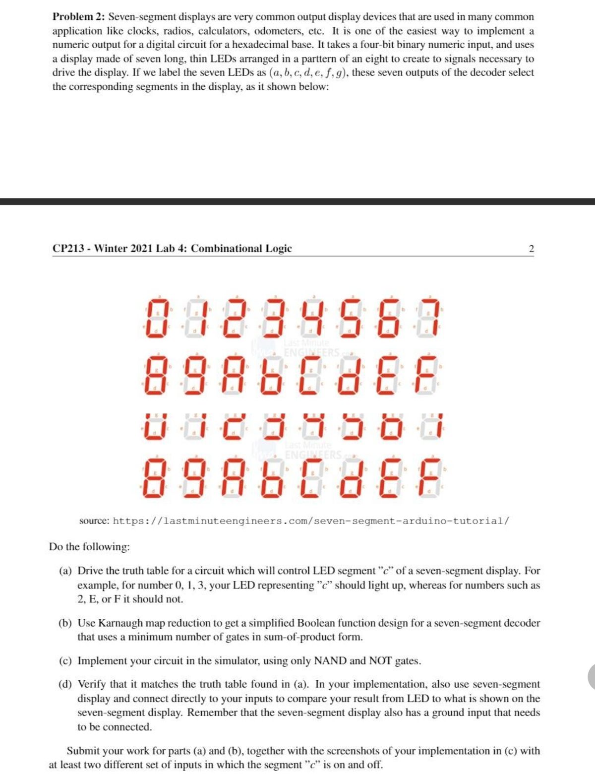

Transcribed Image Text:**Problem 2: Seven-Segment Display**
Seven-segment displays are common output devices used in applications like clocks, radios, calculators, and odometers. They provide an easy method to produce numeric output for digital circuits, especially for hexadecimal bases. The display involves a four-bit binary input and utilizes seven thin LEDs arranged in a pattern to produce the necessary signals for displaying numbers.
In the depiction of segments as labeled \( a, b, c, d, e, f, g \), these outputs from the decoder select the necessary segments to display the corresponding number, as illustrated:
**Diagram Description:**
The diagram shows numbers 0 to F, each represented using a seven-segment layout. Each digit highlights different segments:
- For instance, the number "0" typically lights up segments \( a, b, c, d, e, \) and \( f \).
- The number "1" lights up segments \( b \) and \( c \), and so on.
The diagram visualizes the hexadecimal representation from 0 to F, with each value depicted by lighting up the relevant segments.
**Tasks:**
1. **Truth Table:**
- Create a truth table for a circuit managing segment "c" of the seven-segment display.
- Highlight which numbers activate the "c" segment (e.g., "0", "1", "3").
2. **Karnaugh Map Reduction:**
- Utilize Karnaugh maps to attain a simplified Boolean function for the seven-segment decoder, minimizing gate usage in a sum-of-products form.
3. **Circuit Implementation:**
- Build the circuit using a simulator, employing only NAND and NOT gates.
4. **Verification:**
- Confirm the circuit's accuracy with the truth table.
- Connect directly to inputs and compare LED results with values shown on the display.
- Ensure the ground input of the seven-segment display is connected.
Submit the truth table and Karnaugh map from tasks (a) and (b), alongside screenshots of your simulation proving segment "c" activation for at least two different input sets.
Expert Solution
This question has been solved!
Explore an expertly crafted, step-by-step solution for a thorough understanding of key concepts.

This is a popular solution

Trending nowThis is a popular solution!

Step by stepSolved in 6 steps with 10 images

Knowledge Booster


Learn more about
Need a deep-dive on the concept behind this application? Look no further. Learn more about this topic, electrical-engineering and related others by exploring similar questions and additional content below.Similar questions
- Find Is in the circuit given below 90 kn Is 60 k 30 k 3 Varrow_forwardplease solve this question clearly and perfectly with explanation. I need solution within one hour from now. I will sure like solution and will rate up the work. thanksarrow_forwardCan you please provide and explanation on how to use classical method to solve this problem?arrow_forward
- Find the steady-state currents and Voltages for the circuit shown. Alt R₁ R3 www 000 wwwroo 252 E 50 V 4₁. R₂: икк C₁2 10 5Ω G + >1 www L2RA C₂2 40 +21 www Rs 702arrow_forwardR148 R149 R150 If R148 is 18 Ohms, R149 is 13 Ohms, R150 is 25 Ohms, and there is 4 Amps flowing through R150, what is the current through R148? Please show 3 decimal places and don't include units in your answer (i.e. don't include A in your answer).arrow_forwardplease type so that i can read your solutionarrow_forward
arrow_back_ios
arrow_forward_ios
Recommended textbooks for you
- Introductory Circuit Analysis (13th Edition)Electrical EngineeringISBN:9780133923605Author:Robert L. BoylestadPublisher:PEARSON
 Delmar's Standard Textbook Of ElectricityElectrical EngineeringISBN:9781337900348Author:Stephen L. HermanPublisher:Cengage Learning
 Programmable Logic ControllersElectrical EngineeringISBN:9780073373843Author:Frank D. PetruzellaPublisher:McGraw-Hill Education
  Fundamentals of Electric CircuitsElectrical EngineeringISBN:9780078028229Author:Charles K Alexander, Matthew SadikuPublisher:McGraw-Hill Education
 Electric Circuits. (11th Edition)Electrical EngineeringISBN:9780134746968Author:James W. Nilsson, Susan RiedelPublisher:PEARSON
 Engineering ElectromagneticsElectrical EngineeringISBN:9780078028151Author:Hayt, William H. (william Hart), Jr, BUCK, John A.Publisher:Mcgraw-hill Education,
Introductory Circuit Analysis (13th Edition)
Electrical Engineering
ISBN:9780133923605
Author:Robert L. Boylestad
Publisher:PEARSON
Delmar's Standard Textbook Of Electricity
Electrical Engineering
ISBN:9781337900348
Author:Stephen L. Herman
Publisher:Cengage Learning
Programmable Logic Controllers
Electrical Engineering
ISBN:9780073373843
Author:Frank D. Petruzella
Publisher:McGraw-Hill Education
Fundamentals of Electric Circuits
Electrical Engineering
ISBN:9780078028229
Author:Charles K Alexander, Matthew Sadiku
Publisher:McGraw-Hill Education
Electric Circuits. (11th Edition)
Electrical Engineering
ISBN:9780134746968
Author:James W. Nilsson, Susan Riedel
Publisher:PEARSON
Engineering Electromagnetics
Electrical Engineering
ISBN:9780078028151
Author:Hayt, William H. (william Hart), Jr, BUCK, John A.
Publisher:Mcgraw-hill Education,