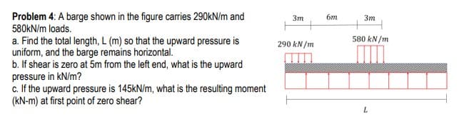
Problem 4: A barge shown in the figure carries 290kN/m and 580KN/m loads. 3m 6m Зт 580 kN/m a. Find the total length, L (m) so that the upward pressure is uniform, and the barge remains horizontal. b. If shear is zero at 5m from the left end, what is the upward pressure in kN/m? c. If the upward pressure is 145KN/m, what is the resulting moment (kN-m) at first point of zero shear? 290 kN /m
Q: A column with a wide-flange section has a flange width b = 250 mm , height h = 250 m m, web…
A: Given dataWIdth of the flange w = 250mmHeight of the flange h = 250mmThinkness of the web tw=…
Q: or the beam illustrated in the figure, find the locations and magnitudes of the maximum tensile…
A:
Q: Problem #7: For the structure below find the maximum absolute vertical shear stress (Oxy) anywhere,…
A: Draw the above structure and mention the load location point as given below. Here RA signifies…
Q: Problem 9 Problem 8.2-11 A hollow pressurized sphere having radius r = 4.8 in. and wall thickness r-…
A: Given data,
Q: Find the Tensions TCA and TCB for the system as shown in figure. Take R = 100 mm, S= 240 mm e = 70°,…
A: Given system with strings 'CA' and 'CB' is shown below. Here, φ=tan-1RS=tan-1100240=22.62°…
Q: For the figure shown below, compute the shear force in section 1. Neglect the weights of the member.…
A:
Q: The cover in the figure is carried by AC and AB ropes. Force in AC rope 4.92 kN, force in AB rope It…
A: Solution:
Q: The cross-sectional dimensions of the beam shown in Figure are ro = 115 mm and ri = 95 mm. Given Mz…
A: Moment of inertia is given asI=π64D4-d4I=π642×1154-2×954I=73.39×106 mm4perpenficular distance…
Q: A countershaft carrying two V-belt pulleys is shown in the figure. Pulley A receives power from a…
A:
Q: Determine the maximum tensile stress σt , maximum compressive stress σc, and maximum shear stress…
A:
Q: One side of a petrol drill pipe, as shown in the figure, has been lifted with the use of a crane P…
A: (a) The cross-sectional diagram of the pipe is shown below.
Q: A safety valve (pressure relieve valve) on top of a pressure vessel containing steam under pressure…
A:
Q: The cantilevered tube shown in the following figure is to be made of 2014 aluminum alloy and is…
A: The tube is subjected to axial loading, bending, and torsion simultaneously, thus there will be…
Q: 8.5-9 A cylindrical pressure vessel with flat ends is sub- jected to a torque Tanda bending moment M…
A: Given Outer radius = 12 in Torque, T = 800 kip. in Bending…
Q: A flanged wooden shape is used to support the loads shown on the beam. The dimensions of the shape…
A: Answer: (a) The maximum tension bending stress is 1530.2124 psi. (b) The maximum compression bending…
Q: The composite beam in the figure is made of steel and aluminum. Beam In steel and aluminum as it is…
A: Given: Esteel=210GPa Eal=70GPa M=2kNm Solution: The position of the neutral axix is exactly at the…
Q: Q2: One side of a petrol drill pipe, as shown in the figure, has been lifted with the use of a crane…
A: The cross-sectional diagram of the pipe is shown below.
Q: Example Fig. 4.19. If permissible stress is 150N/mm2, find its moment of resistance. Compare it with…
A: Area of I section = 7040 mm2 moment of inertia of I section; I = (bd3/12) - (b1d13/12)…
Q: 1. A nitrogen gas storage tank produced by a company has a rotating cylindrical shell and standard…
A:
Q: 250 N 200 N A 2 m 2 m 500 N The bended pipe shown in the figure has a hollow circular cross section…
A: Write the given data with suitable variables.
Q: A flanged wooden shape is used to support the loads shown on the beam. The dimensions of the shape…
A:
Q: 3. Cords are loop around a small spacer separating two cylinders each weighing 400 lb and pass, as…
A:
Q: llow pressurized sphere having radius r = 6.0 in and wall thickness t = 0.5 in is lowered into a…
A: We can apply the thin pressure vessel criteria for the problem because the thickness of the shell is…
Q: 4. A thin-walled cylindrical tank with end caps, seen below, is acted on by an internal pressure p =…
A:
Q: A countershaft carrying two V-belt pulleys is shown in the figure. Pulley A receives power from a…
A: Hello. Since your question has multiple sub-parts, we will solve first three sub-parts for you. If…
Q: A flanged wooden shape is used to support the loads shown on the beam. The dimensions of the shape…
A:
Q: For the system shown in the figure, find the maximum internal shear force in kN. Hint: you will need…
A:
Q: A pressurized cylindrical tank with flat endsis loaded by torques T and tensile forces P (see…
A: Given data as per question The internal pressure p = 7.25 MPa Torque T =850 N .m. t = 6.5 mm
Q: Find the Tensions TCA and TCB for the system as shown in figure. Take R = 180 mm, S= 230 mm 0 = 50°,…
A:
Q: A thin-walled cylindrical pressure vessel of radius r is subjected simultaneously to internal gas…
A:
Q: Example 3.6 The gate in figure below is 5 ft wide, is hinged at point B, and rests against a smooth…
A:
Q: In the ship crane in the figure, at the D and A supports, Find the reaction forces. Section area…
A:
Q: 7. A wooden storage vat is 6 m in diameter and is filled with 7 m of oil, s = 0.8. the wood staves…
A:
Q: A triangular dam is shown in the figure, base is 6-m and height is 8-m. Compute for the factor of…
A:
Q: Problem 2. Each segment of bar ABC has length Z. and shear modulus G and both segments have solid…
A:
Q: 1. For an 8-ft length of gate in the figure, find the compression in strut CD due to water pressure…
A:
Q: Q10: In Figure below,. find the horizontal, vertical forces on the gate ABCD, assume the gate width…
A: First, find the horizontal and vertical force for the triangle portion.
Q: Find the Tensions TCA and TCB for the system as shown in figure. Take R = 200 mm, S= 240 mm 0 = 55°,…
A: Given: The weight is W = 14 kN, The dimension R =200 mm, The dimension S =240 mm, The angle θ=55°.
Q: 2. A sign is supported by a pipe (See figure) having outer diameter Dand inner diameter d. The…
A:
Q: Q5/ A hollow pressurized sphere having radius r=122 mm .and wall thickness t=10mm. is lowered into a…
A:
Q: 3. Given a shear stress of Txy = 5000 psi and a shear modulus of G = 1.15 x 10⁷ psi, find the shear…
A: As per our guidelines, we are supposed to answer only first one question in case of multiple…
Q: For the figure shown below. Find the maximum allowable value of P if the bending stresses are not…
A:
Q: Determination of vertical displacement of Mid-Term Project pipe assembly Find the vertical…
A: Given Data E=200Gpa ****Standard valueA-36 steel Young's Modulus **** G=75Gpa…
Q: Two tubular sections shown in Figure-2, have the same wall thickness and same circumference.…
A: Objective - To find the ratio of shear stresses for equal twisting moments for two cases.
Q: A thick-wall underwater pipe is placed at 20m below sea level. The pipe is carrying compressed…
A:
Q: A Railroad tie
A: Given: The railroad tie is shown below: P = 175 kN b = 300 mm h = 250 mm L = 1500 mm a = 500 mm
Q: In the ship crane in the figure, at the D and A supports, Find the reaction forces. Section area…
A:
Q: The cross-sectional dimensions of the beam shown in Figure are ro = 115 mm and ri = 95 mm. Given Mz…
A:
Step by step
Solved in 2 steps with 1 images
- A pressurized cylindrical tank with flat ends is loaded by torques T and tensile forces P (sec figure), The tank has a radius of r = 125 mm and wall thickness t = 6.5 mm. The internal pressure p = 7.25 MPa and the torque T = 850 N m. (a) What is the maximum permissible value of the forces P if the allowable tensile stress in the wall of the cylinder is 160 MPa? (b) If forces P = 400 kN, what is the maximum acceptable internal pressure in the tank?: A hollow, pressurized sphere having a radius r = 4.8 in, and wall thickness t = 0.4 in. is lowered into a lake (see figure). The compressed air in the tank is at a pressure of 24 psi (gage pressure when the tank: is out of the water). At what depth D0will the wall of the tank be subjected to a compressive stress of 90 psi?A cantilever beam(Z, = 6 ft) with a rectangular cross section (/> = 3.5 in., h = 12 in.) supports an upward load P = 35 kips at its free end. (a) Find the state of stress ((7T, o^., and r in ksi) on a plane-stress element at L/2 that is i/ = 8 in. up from the bottom of the beam. Find the principal normal stresses and maximum shear stress. Show these stresses on sketches of properly oriented elements. (b) Repeat part (a) if an axial compressive centroidal load N = 40 kips is added at B
- A standpipe in a water-supply system (see figure) is 12 ft in diameter and 6 in. thick. Two horizontal pipes carry water out of the standpipe; each is 2 ft in diameter and 1 in. thick. When the system is shut down and water fills the pipes but is not moving, the hoop stress at the bottom of the standpipe is 130 psi, (a) What is the height h of the water in the standpipe? (b) If the bottoms of the pipes are at the same elevation as the bottom of the stand pipe. what is the hoop stress in the pipes?A large precast concrete panel for a warehouse is raised using two sets of cables at two lift lines, as shown in the figure part a. Cable 1 has a length L1 = 22 Ft, cable 2 has a length L2= 10 ft, and the distance along the panel between lift points Band D is d = 14 ft (see figure part b). The total weight of the panel is W = 85 kips. Assuming the cable lift Forces F at each lift line are about equal, use the simplified model of one half of the panel in figure part b to perform your analysis for the lift position shown. Find the required cross-sectional area AC of the cable if its breaking stress is 91 ksi and a factor of safety of 4 with respect to failure is desired.A hemispherical window (or viewport) in a decompression chamber (see figure) is subjected to an internal air pressure of 85 psi. The window is attached to the wall of the chamber by 14 bolts. (a) Find the tensile force Fin each bolt and the tensile stress (T in the viewport if the radius of the hemisphere is 14 in. and its thickness is 1.25 in. (b) If the yield stress for each of the 14 bolts is 50 ksi and the factor of safety is 3.0, Find the required bolt diameter. (c) If the stress in the viewport is limited to 500 psi, find the required radius of the hemisphere.
- A hollow circular tube T of a length L = 15 in. is uniformly compressed by a force P acting through a rigid plate (see figure). The outside and inside diameters of the tube are 3.0 and 2.75 in., respectively. A concentric solid circular bar B of 1.5 in. diameter is mounted inside the lube. When no load is present, there is a clearance c = 0.0I0 in. between the bar B and the rigid plate. Both bar and tube are made of steel having an c[autoplastic stress-strain diagram with E = 29 X LO3 ksi and err= 36 ksi. (a) Determine the yield load Pt- and the corresponding shortening 3yof the lube. (b) Determine the plastic load Ppand the corresponding shortening Spof the tube. (c) Construct a load-displacement diagram showing the load Pas ordinate and the shortening 5 of the tube as abscissa. Hint: The load-displacement diagram is not a single straight line in the region 0 ^ P ^ PrA retaining wall 6 ft high is constructed of horizontal wood planks 2.5 in. thick (actual dimension) that are supported by vertical wood piles of a 12 in, diameter (actual dimension), as shown in the figure. The lateral earth pressure is pt=125 lb/ft2 at the top of the wall and p2= 425 lb/ft2 at the bottom. Assuming that the allowable stress in the wood is 1175 psi, calculate the maximum permissible spacing s of the piles. Find the required diameter of the wood piles so that piles and planks (f = 2.5 in.) reach the allowable stress at the same time. Hint: Observe that the spacing of the piles may be governed by the load-carrying capacity of either the planks or the piles. Consider the piles to act as cantilever beams subjected to a trapezoidal distribution of load, and consider the planks to act as simple beams between the piles. To be on the safe side, assume that the pressure on the bottom plank is uniform and equal to the maximum pressure.A beam with a width h = 6 in. and depth h = 8 in. is simply supported at A and B. The beam has a length L = 10 ft and is subjected to a linearly varying distributed load with peak intensity q0= 1500 lb/ft. Calculate the state of plane stress at point C located 3 in. below the top of the beam and 0.1 ft to the left of point B. Also find the principal stresses on element C. Neglect the weight of the beam.
- A steel post (E=30×106) having thickness t = 1/8 in. and height L = 72 in. support a stop sign (see figure), where s = 12.5 in. The height of the post L is measured from the base to the centroid of the sign. The stop sign is subjected to wind pressure p = 20 lb/ft2 normal to its surface. Assume that the post is fixed at its base. What is the resultant load on the sign? (Sec Appendix E, Case 25, for properties of an octagon, n =8.) What is the maximum bending stress in the post? Repeat part (b) if the circular cut-outs arc eliminated over the height of the post.A large spherical tank (see figure) contains gas at a pressure of 420 psi. The tank is 45 ft in diameter and is constructed of high-strength steel having a yield stress in tension of 80 ksi. (a) Determine the required thickness (to the nearest 1/4 inch) of the wall of the tank if a factor of safety of 3,5 with respect to yielding is required. (b) If the tank wall thickness is 2.25 in., what is the maximum permissible internal pressure?A foot bridge on a hiking trail is constructed using two timber logs each having a diameter d = 0.5 m (see figure a). The bridge is simply supported and has a length L = 4 m. The top of each log is trimmed to form the walking surface (see Fig, b)LA simplified model of the bridge is shown in Fig. g. Each log must carry its own weight w = 1.2 kN/m and the weight (P = 850 N) of a person at mid-span, (see Fig. b). Determine the maximum tensile and compressive stresses in the beam (Fig, b) due to bending. If load h is unchanged, find the maximum permissible value of load ... if the allowable normal stress in tension and compression is 2.5 M Pa.