For the system shown in the figure, find the maximum internal shear force in kN. Hint: you will need to draw a shear-moment diagram. 10 kN /m 90 kN 50 kNm 3m 2 m 5 m 4 m 3m
For the system shown in the figure, find the maximum internal shear force in kN. Hint: you will need to draw a shear-moment diagram. 10 kN /m 90 kN 50 kNm 3m 2 m 5 m 4 m 3m

Mechanics of Materials (MindTap Course List)
9th Edition
ISBN:9781337093347
Author:Barry J. Goodno, James M. Gere
Publisher:Barry J. Goodno, James M. Gere
Chapter5: Stresses In Beams (basic Topics)
Section: Chapter Questions
Problem 5.9.4P: A circular pole is subjected to linearly varying distributed force with maximum intensity t0....

Related questions
Question
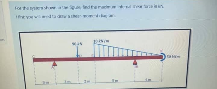
Transcribed Image Text:For the system shown in the figure, find the maximum internal shear force in kN.
Hint: you will need to draw a shear-moment diagram.
son
10 kN /m
90 kN
50 kNm
3m
2 m
5m
4 m
3m
Expert Solution
This question has been solved!
Explore an expertly crafted, step-by-step solution for a thorough understanding of key concepts.

Step by step
Solved in 2 steps with 2 images

Knowledge Booster


Learn more about
Need a deep-dive on the concept behind this application? Look no further. Learn more about this topic, mechanical-engineering and related others by exploring similar questions and additional content below.Recommended textbooks for you
Mechanics of Materials (MindTap Course List)
Mechanical Engineering
ISBN:
9781337093347
Author:
Barry J. Goodno, James M. Gere
Publisher:
Cengage Learning
Mechanics of Materials (MindTap Course List)
Mechanical Engineering
ISBN:
9781337093347
Author:
Barry J. Goodno, James M. Gere
Publisher:
Cengage Learning