
Introductory Circuit Analysis (13th Edition)
13th Edition
ISBN: 9780133923605
Author: Robert L. Boylestad
Publisher: PEARSON
expand_more
expand_more
format_list_bulleted
Related questions
Question
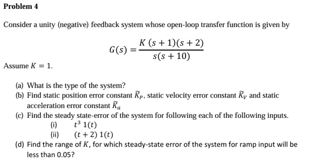

Transcribed Image Text:Problem 4
Consider a unity (negative) feedback system whose open-loop transfer function is given by
K(s+1)(s+2)
G(s):
s(s +10)
Assume K = 1.
(a) What is the type of the system?
(b) Find static position error constant Kp, static velocity error constant Ky and static
acceleration error constant Ka
(c) Find the steady state-error of the system for following each of the following inputs.
(i)
(!!)
t³ 1(t)
(t+2) 1(t)
(d) Find the range of K, for which steady-state error of the system for ramp input will be
less than 0.05?
Expert Solution
This question has been solved!
Explore an expertly crafted, step-by-step solution for a thorough understanding of key concepts.

Step by stepSolved in 2 steps with 4 images

Knowledge Booster

Similar questions
- Consider the feedback system. It is known that G(s) has one unstable zero and one unstable pole. On the G(s)-plane -1+j0 point is encircled one time in the clockwise direction as s moves in the clockwise direction on the Nyquist path. What can be said about the closed-loop system? a. Stable O b. C. e. Of. G(s) Has 1 unstable pole Od. Has 2 unstable poles and 1 stable zero Has 1 unstable pole and 1 unstable zero Has 2 unstable poles and 2 unstable zeros Has 2 unstable poles and 1 ustable zero None g.arrow_forwardA unity feedback system has the characteristic equation shown below. For some gain K the unity feedback system enters into a state of self-sustained oscillations. Use the Routh - Hurwitz Stability Criterion to find the frequency of this self-sustained oscillation in rad/ sec. Enter your answer in decimal form to two decimal places. 4 + 65³ +12s² + 10s + (3+K)arrow_forwardQ.2) For the below unity feedback system shown in figure a, M(s) is added (as shown in figure b) to make an error at the steady-state to be zero, if you know that the input R(s) is a c- Unit-parabolic a- Unit step b- Unit ramp Evaluate M(s) which perform the mentioned function? R(s) G(s) M(s) Cts) R() G(s) C(s) (а) (b)arrow_forward
- i need the answer quicklyarrow_forward8nnarrow_forwardThe unity feedback system with open loop transfer function G(s) K S² is to be designed to have closed loop poles at -2.4 + j4.16. If the compensator's zero is placed at -1, do the following: a) Find the compensator pole b) Find the system gain c) Find the location of the third pole. d) Evaluate the steady-state error characteristic. e) Plot the step response of the compensated systemarrow_forward
- Please help me with this question! Thanks!arrow_forwardClear answerarrow_forwardCopy the control system shown in Figure Q2 into your answer book, labelling the actual output, control signal, desired output, plant, feedback and error signal. Q2 (a) 2 Σ K+ K, (s+1)(s+2) Figure Q2 (b) Determine the closed-loop transfer function for the system shown in Figure Q2 and hence obtain the characteristic equation for the system. Using Routh 's stability criterion, find the range of the controller gains (K, Ki) for which this system is stable. (c) For the system shown in Figure Q2, find the frequency, jo, and gain, Kı, for which the root locus crosses the imaginary axis (assume K = 1). (d) (e) What would you expect to see for the frequency, calculated in part (d), when you decrease K below 1.arrow_forward
- QUESTION4 Consider the feedback system in the figure with G(s) Using the Ziegler-Nichols Oscillation Method. %3D (s+1)(s+3)(s+10) for an ideal PID controller C(s) - K, ++ Kps determine the gains K K, and K. Choose the closest set of gains. C(s) G(s) OK, - 18, K, = 12.81, K, = 6.32 O Kp = 4.80, K, = 2.65, Kp = 2.18 O Kp - 47.52, K, = 85.57, K, - 12.60 %3D O K, - 68.64, K, = 143.27, Kp = 8.22arrow_forwardCALCULATE Q 4 PART A B i, iiarrow_forwardHG(s) = QUESTION 6 s²+4s+5 Consider the root locus of a unity feedback system that has the open loop transfer function shown below. Find the break point. K(s+1) ² $3 HG(s) = AKI a... bmit. Click Save All Answers to save all answers.arrow_forward
arrow_back_ios
SEE MORE QUESTIONS
arrow_forward_ios
Recommended textbooks for you
- Introductory Circuit Analysis (13th Edition)Electrical EngineeringISBN:9780133923605Author:Robert L. BoylestadPublisher:PEARSON
 Delmar's Standard Textbook Of ElectricityElectrical EngineeringISBN:9781337900348Author:Stephen L. HermanPublisher:Cengage Learning
 Programmable Logic ControllersElectrical EngineeringISBN:9780073373843Author:Frank D. PetruzellaPublisher:McGraw-Hill Education
  Fundamentals of Electric CircuitsElectrical EngineeringISBN:9780078028229Author:Charles K Alexander, Matthew SadikuPublisher:McGraw-Hill Education
 Electric Circuits. (11th Edition)Electrical EngineeringISBN:9780134746968Author:James W. Nilsson, Susan RiedelPublisher:PEARSON
 Engineering ElectromagneticsElectrical EngineeringISBN:9780078028151Author:Hayt, William H. (william Hart), Jr, BUCK, John A.Publisher:Mcgraw-hill Education,
Introductory Circuit Analysis (13th Edition)
Electrical Engineering
ISBN:9780133923605
Author:Robert L. Boylestad
Publisher:PEARSON
Delmar's Standard Textbook Of Electricity
Electrical Engineering
ISBN:9781337900348
Author:Stephen L. Herman
Publisher:Cengage Learning
Programmable Logic Controllers
Electrical Engineering
ISBN:9780073373843
Author:Frank D. Petruzella
Publisher:McGraw-Hill Education
Fundamentals of Electric Circuits
Electrical Engineering
ISBN:9780078028229
Author:Charles K Alexander, Matthew Sadiku
Publisher:McGraw-Hill Education
Electric Circuits. (11th Edition)
Electrical Engineering
ISBN:9780134746968
Author:James W. Nilsson, Susan Riedel
Publisher:PEARSON
Engineering Electromagnetics
Electrical Engineering
ISBN:9780078028151
Author:Hayt, William H. (william Hart), Jr, BUCK, John A.
Publisher:Mcgraw-hill Education,