The simple beam ACB shown in the figure is subjected to a concentrated load P 30 kips and a distributed load q =3kips/ft acting at different parts. (1) Determine the reaction forces Ra and Rc. A (2) Draw the shear-force and bending-moment diagrams for this beam., (3) Determine the location and magnitude of the maximum normal stress due to bending, if the section modulus of the beam is S. 3 kips/ft 30 kips в 6 ft 3 ft M
The simple beam ACB shown in the figure is subjected to a concentrated load P 30 kips and a distributed load q =3kips/ft acting at different parts. (1) Determine the reaction forces Ra and Rc. A (2) Draw the shear-force and bending-moment diagrams for this beam., (3) Determine the location and magnitude of the maximum normal stress due to bending, if the section modulus of the beam is S. 3 kips/ft 30 kips в 6 ft 3 ft M

Mechanics of Materials (MindTap Course List)
9th Edition
ISBN:9781337093347
Author:Barry J. Goodno, James M. Gere
Publisher:Barry J. Goodno, James M. Gere
Chapter5: Stresses In Beams (basic Topics)
Section: Chapter Questions
Problem 5.10.7P: A cantilever beam AB of length L = 6.5 ft supports a trapezoidal distributed load of peak intensity...

Related questions
Question
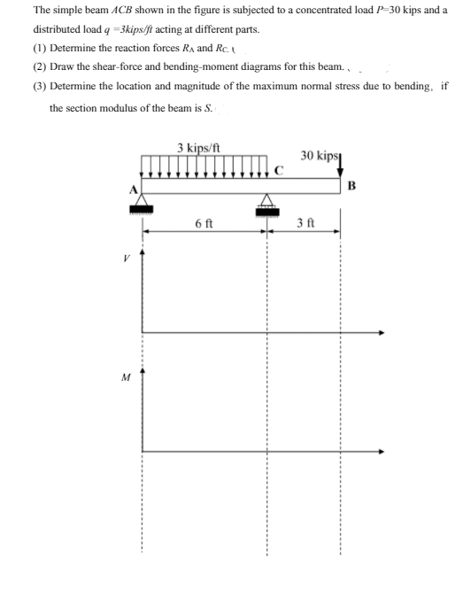
Transcribed Image Text:The simple beam ACB shown in the figure is subjected to a concentrated load P-30 kips and a
distributed load q =3kips/ft acting at different parts.
(1) Determine the reaction forces RA and Rc.
(2) Draw the shear-force and bending-moment diagrams for this beam.,
(3) Determine the location and magnitude of the maximum normal stress due to bending, if
the section modulus of the beam is S.
3 kips/ft
30 kips
B
6 ft
3 ft
M
Expert Solution
This question has been solved!
Explore an expertly crafted, step-by-step solution for a thorough understanding of key concepts.

This is a popular solution!

Trending now
This is a popular solution!

Step by step
Solved in 4 steps with 2 images

Knowledge Booster


Learn more about
Need a deep-dive on the concept behind this application? Look no further. Learn more about this topic, mechanical-engineering and related others by exploring similar questions and additional content below.Recommended textbooks for you
Mechanics of Materials (MindTap Course List)
Mechanical Engineering
ISBN:
9781337093347
Author:
Barry J. Goodno, James M. Gere
Publisher:
Cengage Learning
Mechanics of Materials (MindTap Course List)
Mechanical Engineering
ISBN:
9781337093347
Author:
Barry J. Goodno, James M. Gere
Publisher:
Cengage Learning