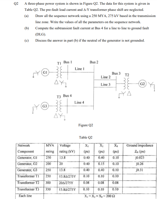
Q2 A three-phase power system is shown in Figure Q2. The data for this system is given in Table Q2. The pre-fault load current and A-Y transformer phase shift are neglected. (a) Draw all the sequence network using a 250 MYA, 275 kV based in the transmission line zone. Write the values of all the parameters on the sequence network. (b) Compute the subtransient fault current at Bus 4 for a line to line to ground fault (DLG). (c) Discuss the answer in part (b) if the neutral of the generator is not grounded.
Q2 A three-phase power system is shown in Figure Q2. The data for this system is given in Table Q2. The pre-fault load current and A-Y transformer phase shift are neglected. (a) Draw all the sequence network using a 250 MYA, 275 kV based in the transmission line zone. Write the values of all the parameters on the sequence network. (b) Compute the subtransient fault current at Bus 4 for a line to line to ground fault (DLG). (c) Discuss the answer in part (b) if the neutral of the generator is not grounded.

Power System Analysis and Design (MindTap Course List)
6th Edition
ISBN:9781305632134
Author:J. Duncan Glover, Thomas Overbye, Mulukutla S. Sarma
Publisher:J. Duncan Glover, Thomas Overbye, Mulukutla S. Sarma
Chapter3: Power Transformers
Section: Chapter Questions
Problem 3.45P: Figure 3.39 shows a oneline diagram of a system in which the three-phase generator is rated 300 MVA,...

Related questions

Question
Transcribed Image Text:Q2
A three-phase power system is shown in Figure Q2. The data for this system is given in
Table Q2. The pre-fault load current and A-Y transformer phase shift are neglected.
(a)
Draw all the sequence network using a 250 MYA, 275 kV based in the transmission
line zone. Write the values of all the parameters on the sequence network.
(b)
Compute the subtransient fault current at Bus 4 for a line to line to ground fault
(DLG).
(c)
Discuss the answer in part (b) if the neutral of the generator is not grounded.
Bus 2
TI Bus I
Line I
(GI
Bus 3
T2
Line 2
AY
Line 3
G2
Тз Bus 4
YA
Line 4
G3
AY
Figure Q2
Table Q2
Voltage
Ground impedance
Network
|Component
Generator, G1
Generator, G2
Generator, G3
Transformer TI
MVA
X2
X,
rating rating (kV)
(pu)
(pu)
(pu)
ZN (pu)
250
13.8
0.40
0.40
0.10
j0.023
200
20
0.40
0.15
0.10
j0.26
250
13.8
0.40
0.40
0.10
j0.31
250
13.8A/275Y
0.10
0.10
0.10
Transformer T2
Transformer T3
300
20Δ/275Y
0.08
0.08
0.08
350
13.8A/275Y
0.10
0.10
0.10
Each line
X, = X; = X, = 200 2
Expert Solution
This question has been solved!
Explore an expertly crafted, step-by-step solution for a thorough understanding of key concepts.

Step by step
Solved in 8 steps with 6 images

Knowledge Booster


Learn more about
Need a deep-dive on the concept behind this application? Look no further. Learn more about this topic, electrical-engineering and related others by exploring similar questions and additional content below.Recommended textbooks for you
Power System Analysis and Design (MindTap Course …
Electrical Engineering
ISBN:
9781305632134
Author:
J. Duncan Glover, Thomas Overbye, Mulukutla S. Sarma
Publisher:
Cengage Learning
Power System Analysis and Design (MindTap Course …
Electrical Engineering
ISBN:
9781305632134
Author:
J. Duncan Glover, Thomas Overbye, Mulukutla S. Sarma
Publisher:
Cengage Learning