
Introductory Circuit Analysis (13th Edition)
13th Edition
ISBN: 9780133923605
Author: Robert L. Boylestad
Publisher: PEARSON
expand_more
expand_more
format_list_bulleted
Related questions
Concept explainers
Question
Answer quickly
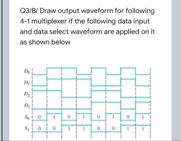

Transcribed Image Text:Q3/B/ Draw output waveform for following
4-1 multiplexer if the following data input
and data select waveform are applied on it
as shown below
Do
Dy
D2
Dy
So
TLEE
Expert Solution
This question has been solved!
Explore an expertly crafted, step-by-step solution for a thorough understanding of key concepts.

This is a popular solution

Trending nowThis is a popular solution!

Step by stepSolved in 2 steps with 1 images

Knowledge Booster


Learn more about
Need a deep-dive on the concept behind this application? Look no further. Learn more about this topic, electrical-engineering and related others by exploring similar questions and additional content below.Similar questions
- Consider as a simple telephone network consisting of two end workplacesand one intermediate switch with a 1 MHz full duplex trunk between eachend workplace and the intermediate switch. Assume a 4 kHz channel foreach voice call. The telephone is used to make four calls per 8 hour workdayin average, with mean call duration of five minutes. Twelve percent of thecalls are long distance. Analyse and determine the maximum number oftelephones an end workplace can support. Note: Please explain the answer process clearly.arrow_forwardThe Vrms value is wrongarrow_forward858445655 O Blackboard Remaining Time: 59 minutes, 28 seconds. * Question Completion Status: 90 10 110 120 130 14D 150 160 440 450 46D 470 480 49D 500 10 70 18 19 201 40 50 36 370 38 3940 410 42 43D 20 QUESTION 35 What is indicator number 1 called. 6 1 Heading indicator Airspeed indicator O Altimeter indicator QUESTION 36 Attitude indicator is also known as: O Virtual horizon O Visual Horizon O Artificial Horizon Th Click Save and Submit to save and submit. Click Save All Answers to save all answers. MacBook Airarrow_forward
- Refer to the National Electrical Code® or the working drawings when necessary. Where applicable, responses should be written in complete sentences. For problems 1 and 2, six luminaires, similar to Style E used in the Commercial Building, are to be installed in a room that is 12 ft x 18 ft (~3.7 m x ~5.5 m) with a 9 ft (2.8 m) floor-to-ceiling height. The spacing ratio for the luminaire is 1:0. 1. The maximum distance that the luminaires can be separated and achieve uniform illuminance is ft ( m). For problems 2-5, two luminaires, 8 ft (2.5 m) and 4 ft (1.2 m) in length with dimensions as shown in Figure 15-7, are to be installed in tandem (end to end). The end of the long luminaire is to be 2 ft (600 mm) from the wall. 2. The center of the outlet box should be roughed in at ft ( m) from the wall. 3. The first support should be installed at the wall. ft ( m) from 4. The second support should be installed at from the wall. ft ( m) 5. The final support should be installed at the wall. ft…arrow_forwardA.a.Two electricians are discussing industrial cabling. Electrician A says that copper cable provides clearer transmission signals than fiber optic cable. Electrician B says that fiber optic cables will be larger thancopper cables with identical data transmission rates. Who is correct?B. Both Electrician A and Electrician B are correct.C. Only Electrician A is correct.D. Neither Electrician A nor Electrician B is correct. A.b. Two electricians are discussing industrial cabling. Electrician A says that signal losses in fiber optic cableare more likely to be caused by splices and connectors than cable length. Electrician B says that wire-wrapterminations should be used when there isn't enough time available to use IDC terminations. Who iscorrect?A. Only Electrician A is correct.B. Both Electrician A and Electrician B are correct.C. Only Electrician B is correct.arrow_forwardplease answer in hand written i dont understand where i can put the exponent..arrow_forward
arrow_back_ios
arrow_forward_ios
Recommended textbooks for you
- Introductory Circuit Analysis (13th Edition)Electrical EngineeringISBN:9780133923605Author:Robert L. BoylestadPublisher:PEARSON
 Delmar's Standard Textbook Of ElectricityElectrical EngineeringISBN:9781337900348Author:Stephen L. HermanPublisher:Cengage Learning
 Programmable Logic ControllersElectrical EngineeringISBN:9780073373843Author:Frank D. PetruzellaPublisher:McGraw-Hill Education
  Fundamentals of Electric CircuitsElectrical EngineeringISBN:9780078028229Author:Charles K Alexander, Matthew SadikuPublisher:McGraw-Hill Education
 Electric Circuits. (11th Edition)Electrical EngineeringISBN:9780134746968Author:James W. Nilsson, Susan RiedelPublisher:PEARSON
 Engineering ElectromagneticsElectrical EngineeringISBN:9780078028151Author:Hayt, William H. (william Hart), Jr, BUCK, John A.Publisher:Mcgraw-hill Education,
Introductory Circuit Analysis (13th Edition)
Electrical Engineering
ISBN:9780133923605
Author:Robert L. Boylestad
Publisher:PEARSON
Delmar's Standard Textbook Of Electricity
Electrical Engineering
ISBN:9781337900348
Author:Stephen L. Herman
Publisher:Cengage Learning
Programmable Logic Controllers
Electrical Engineering
ISBN:9780073373843
Author:Frank D. Petruzella
Publisher:McGraw-Hill Education
Fundamentals of Electric Circuits
Electrical Engineering
ISBN:9780078028229
Author:Charles K Alexander, Matthew Sadiku
Publisher:McGraw-Hill Education
Electric Circuits. (11th Edition)
Electrical Engineering
ISBN:9780134746968
Author:James W. Nilsson, Susan Riedel
Publisher:PEARSON
Engineering Electromagnetics
Electrical Engineering
ISBN:9780078028151
Author:Hayt, William H. (william Hart), Jr, BUCK, John A.
Publisher:Mcgraw-hill Education,