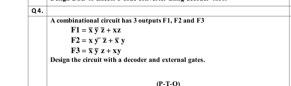
Q4. A combinational circuit has 3 outputs F1, F2 and F3 F1 = xy Z+ xz F2 = x y Z+x y F3 = x y z + xy Design the circuit with a decoder and external gates.


Q: نقطة واحدة A synchronous state machine has two inputs (X1 and X2) and one output (Z). The…
A: 8
Q: A combinational logic circuit has an output F=a'b'c+a'c'd'+bc'd+acd. A * ;static one hazard occurs…
A: None of the above
Q: С. Figure Q1 (c) shows a logic circuit with four inputs A, B, C, D and one output Y. Redraw the…
A: In the given circuit we have Not gate, AND gate, OR gate used. you can use NAND gate as follows:
Q: A sequential circuit has two JK flip-flops A and B, two inputs x and y, and one output z. The…
A: Given Data:
Q: Question 2 A combinational circuit is defined by the three Boolean functions below. Design the…
A:
Q: 6. Design the circuit diagram and truth table for the Boolean expression : F = (A’B) + (C’B).
A: 5. I solved the only question according to Bartleby guidelines. The decoder is shown below, Since…
Q: A combinational circuit is defined by the following Boolean functions. Design the cırcuit with a…
A: Circuit with 3x8 decoder and OR gates:
Q: A 4bit x 4bit DIVIDER circuit can be designed using AND gates, Full Substractor and Magnitude…
A: A 4bit x 4bit DIVIDER circuit can be designed using AND gates. Full Subtractor and Magnitude…
Q: 3. A COMBINATIONAL CIRCUIT IS DEFINED BY THE FOLLOWING THREE BOOLEAN FUNCTIONS. DESIGN THE CIRCUIT…
A: Circuit Diagram with Decoder and logic gate is detailed in step 2.
Q: Q3// 1-Use Two Half adder and only one NOR gate to design magnitude comparator circuit. This circuit…
A: 1.
Q: Given a 4-bit signed input P=P3P2P1P0 and a control input Z, use a 4-bit adder and any logic gates…
A: 4-bit signed input P=P3P2P1P0 control input Z 4 bit added
Q: A combinational logic circuit has an output F=a'b'c+a'c'd'+bc'd+acd. To remove the static one hazard…
A: a combinational logic circuit has an output F=a'b'c+a'c'd'+bc'd+acd To remove the static one…
Q: öislg äbäi A synchronous state machine has two inputs (X1 and X2) and one output (Z). The…
A: The solution to the given problem is below.
Q: Design an arithmetic circuit with one selection variable S and two n-bit data inputs A and B. The…
A: Answer: Arithmetic circuit: The design of an arithmetic circuit with the selection variable S and…
Q: combinational circuit is defined by the following three Boolean functions. Design the circuit with a…
A: The answer of this question is as follows:
Q: Q1. Design a 4-input, one output combinational logic circuit for the following input-output…
A: Given:
Q: the circuit with a decoder and external gates
A: A combinational circuit has 2 outputs F1 and F2 the circuit with a decoder and external gates
Q: Question 1 : Consider the following combinational circuit (3 inputs: A, B and C- 2 outputs: X and Y)
A:
Q: Construct the circuit of the following function using 3:8 decoder and 2:4 decoder only: F(A,B,C,D)…
A: The given function is
Q: The operation F(X, Y, Z) = (!X + !Y + !Z) can be implemented with a single input signals and one…
A: Here in this question we have given a some boolean expression and we have asked to implement with…
Q: A combinational logic circuit has three inputs equence A, B, and C and two outputs with seque d Y.…
A:
Q: Design a combinational circuit with four inputs, w, x, y, and z, and four outputs, A, B, C and D.…
A: Lets see the solution.
Q: 4-7. Design a combinational circuit that multiplies by 5 an input decimal digit represented in BCD.…
A: Make a digital circuit that takes a BCD digit as input and produces the output that is equal to 5…
Q: A synchronous state machine has two inputs (X1 and X2) and one نقطة واحدة output (Z). The…
A: The solution to the given problem is below.
Q: Design 4-input ( D,A,W,O) one output (y) conbinational logic circuit for the following input- output…
A: We are given for input (D,A,W,O) and one output that is y. We have to design a combinational logic…
Q: QUESTION 3 Using a decoder and external gates, design the combinational circuit defined by the…
A: Given:
Q: The output of a three input AND gate (with inputs A, B and C) is equal to 1 when O a. A=0, B=0, C=0…
A: The 3-input Logic AND Gate is given below: Symbol Truth Table 3-input AND Gate C B A Q…
Q: The following three Boolean functions define a combinational circuit. Design the Circuit with a…
A: Here we will use one decoder to define the three function together. The size of decoder that will…
Q: 3. Draw the logic gate circuitry for the following Boolean expressions using NAND gates only c)…
A: Given Boolean expressions is F= AB+ (AC)' F= (A+B)' (C+D)C' Total inputs - A,B,C Total outputs -…
Q: The output of a combinational logic circuit is F=A'D'+(A+B) (B'+C'). To remove the static one hazard…
A: If there is an accident in the digital circuit, it can cause temporary fluctuations in the circuit…
Q: 3. The following figure shows a transistor-level logic gate for AND gate. Complete the table. A 0 0…
A: answer is
Q: Using a decoder and external gates, design the combinational circuit defined by the following three…
A: Decoder A decoder is a digital circuit that converts a code into a set of signals. A simple…
Q: Universal Gates Exercise: Redraw the below logic diagram. The new circuit have to consist of AND and…
A: Given logic diagram contains six inputs that are A, B, C, D, E and F. In the given diagram it…
Q: Q4// Design a combinational circuit with three inputs, A, B, and C, and three outputs,x, y, and z.…
A:
Q: 1- A combinational circuit is defined by the following three functions: F1= XY+XYZ F2= XY + XYZ F3=…
A: 1- A combinational circuit is defined by the following three functions: F1= 2 + XYZ F2= X? + feYZ…
Q: following combinational circuit (3 inputs: A, B and C- 2 outputs: X and Y) x1 B x1 C x1 x1 b- Redraw…
A: check further steps for the answer :
Q: 3. Draw an alternate logic symbol sometimes used to show a NAND gate (has inverted inputs). 4. Draw…
A: NAND gate can be formed with the help of NOR gate:
Q: The combinational logic circuit required for this system is only 4x1 Design using data selectors…
A: Multiplexing is the general term for transmitting one or more analog or digital signals at varying…
Q: Simplify the given Boolean function and design its logic gates F2(x,y,z) = xy’+xz+y’z’
A: F2(x,y,z) = xy’+xz+y’z’ We know a+a'=1 F2(x,y,z) = xy’(z+z')+xz(y+y')+y’z’(x+x') F2(x,y,z) =…
Q: A synchronous state machine has two inputs (X1 and X2) and one output (Z). The relationship between…
A: the asynchronous state machine has two inputs (x1 and x2) and one output (z). the relationship…
Q: Designs a logic circuit that will allow a signal to pass to the output only when control inputs B…
A: Designs a logic circuit that will allow a signal to pass to the output only when control inputs B…
Q: 3. A logic circuit has three inputs (x,x,x,) representing an unsigned binary number. The output D is…
A: To design a logic circuit that has three inputs (X2X1X0) representing an unsigned binary number. The…
Q: Construct the circuit of the following function using 3:8 decoder and 2:4 decoder only: F(W,X,Y,Z)…
A: Answer : given : F(W,X,Y,Z)=(Y'+X)(W+X)
Q: Write the two outputs of S and C, in terms of the four inputs A, B and C, for the follow logic gates…
A: The used gated in the logic circuit are 2 XOR gates, 2 AND gates and 1 OR gate The output equations…
Q: The operation F(X, Y) = (!X * Y) + (X * !Y) can be implemented with a single gate with two input…
A: Solution - In the given question, we have to find the gate which can implemented the given…
Q: A combinational logic circuit has an output F=a'b'c+a'c'd'+bc'd+acd. To remove the static one hazard…
A:
Q: Q.3) Design a JK FF using: a) an SR FF and minimum gates. b) a D FF and minimum gates. c) a T FF and…
A: answer starts from step 2
Q: Design a 4:1 MUX in multiple ways: a) Using basic gates b) Using tri-state logic c) Using 2:1 MUXes…
A:
Q: Using NAND gates, one 3-8 decoder, and 1 2-1 MUX, design a combination circuit with two outputs…
A:
Q: F1 = xyZ + xz F2 = x y Z+Xy F3 = xỹ z + xy
A: F1=x'y'z'+xz = x'y'z'+xz(y+y') = x'y'z'+xyz+xy'z = x'y'z'+xy'z+xyz = Σ (0,5,7) F2=xy'z'+x'y =…


Trending now
This is a popular solution!

Step by step
Solved in 2 steps with 2 images


- 3. A COMBINATIONAL CIRCUIT IS DEFINED BY THE FOLLOWING THREE BOOLEAN FUNCTIONS. DESIGN THE CIRCUIT WITH A DECODER AND EXTERNAL GATES F1= X'Y'Z' + XZ F2= XY'Z' + X'Y F3= X'Y'Z + XYUsing a decoder and external gates, design the combinational circuit defined by the following three Boolean functions:1. (a) F 1 = x ′ y z ′ + x z F 2 = x y ′ z ′ + x ′ y F 3 = x ′ y ′ z ′ + x y2. (b) F 1 = ( y ′ + x ) z F 2 = y ′ z ′ + x ′ y + y z ′ F 3 = ( x + y ) zA combinational circuit is defined by the following three Boolean functions. Design the circuit with a decoder and external gates. F1 = x' y' z' + xzF2 = x y' z' + x'yF3 = x' y' z + xy
- 5. Design an appropriate combinational circuit that implements a digital system with the following output functions: ROR, SHL, AND, XOR, ADD, DIV, SUB, MOV using a decoder. 6. Design the circuit diagram and truth table for the Boolean expression : F = (A’B) + (C’B).2. Design and implement a combinational circuit that adds three bits (x,y, and z) and returns the sum S and carry C.A combinational circuit has 2 outputs F1 and F2?? (x, y, z) = Ʃ m (1,2,4,7)?2 (x, y, z) = Ʃ m ( 3,5,6,7)Design the circuit with a decoder and external gates.
- 1) Build the truth table for this circuit by cycling through all of the possible input combinations and noting the input. 2) What logical function does this circuit represent? 3) Is it possible to replace this circuit by an equivalent single gate? 4) What would equivalence mean in this case?A sequential circuit has two JK flip-flops A and B, two inputs x and y, and oneoutput z. The flip-flop input equations and circuit output equation areJ A = B’y + Bx’ K A = B’xy’J B = A’x’ K B = (A’)’ + x’y’Z = Axy + B’xy’(a) Draw the logic diagram of the circuit.(b) Tabulate the state table.(c) Derive the state equations for A and BKarnaugh Map And Circuit Designing – 4 Bits Plus Or Minus 1Design a circuit with inputs x, y, z and w. When the binary input is 0, 1, 2, 3,4,5,6, and 7 thebinary output is one greater than the input. When the binary input is 8, 9, 10, 11, 12,13,14, and15 the binary output is one less than the input.
- Consider an OAI321 static CMOS gate.(a) Draw the logic diagram (i.e. using AND/OR/INVERTER gates)(b) Draw the transistor schematic (using NFET/PFETs)Q1 Using a multiplexer design a combinational circuit design defined by the following boolean expression: F= y'z'+x'y+yzA majority circuit is a combinational circuit whose output is equal to 1 if the input variables have more 1’s than 0’s. The output is 0 otherwise.1. (a) Design a three-input majority circuit by finding the circuit’s truth table, Boolean equation, and a logic diagram.2. (b) Write and verify a HDL gate-level model of the circuit.