QUESTION 3 A pattern detector which gives 1 at its 1-bit output when the last four values of its 1-bit input are 1011 will be designed. D flip-flops, AND,OR gates will be used for implementation. a) Draw the state diagram b) Draw the state table. c) Drive the flip-flop input and output Boolean equations. d) Draw the circuit.
QUESTION 3 A pattern detector which gives 1 at its 1-bit output when the last four values of its 1-bit input are 1011 will be designed. D flip-flops, AND,OR gates will be used for implementation. a) Draw the state diagram b) Draw the state table. c) Drive the flip-flop input and output Boolean equations. d) Draw the circuit.

Chapter22: Sequence Control
Section: Chapter Questions
Problem 6SQ: Draw a symbol for a solid-state logic element AND.

Related questions
Question
Course name : Digital system
Electrical engineering
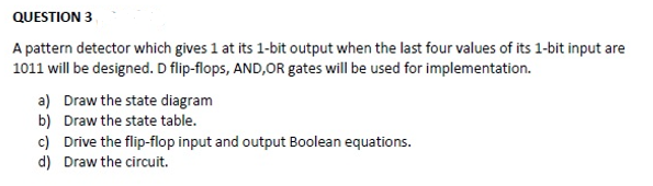
Transcribed Image Text:QUESTION 3
A pattern detector which gives 1 at its 1-bit output when the last four values of its 1-bit input are
1011 will be designed. D flip-flops, AND,OR gates will be used for implementation.
a) Draw the state diagram
b) Draw the state table.
c) Drive the flip-flop input and output Boolean equations.
d) Draw the circuit.
Expert Solution
This question has been solved!
Explore an expertly crafted, step-by-step solution for a thorough understanding of key concepts.

Step by step
Solved in 6 steps with 6 images

Knowledge Booster


Learn more about
Need a deep-dive on the concept behind this application? Look no further. Learn more about this topic, electrical-engineering and related others by exploring similar questions and additional content below.Recommended textbooks for you