Refer the following figure. If a bypass capacitor is connected across RE, the value the resistance, looking in at the base, is equal to ------. +20 V Rc $2.5 kn 1 uF HEo Vout 22 kn 1 uF Vin HE Poc -Ba- 100 RE 500 n O a. 5 kn O b. 416 2 O . 50 kn O d. 500 N
Q: 2) Two parallel-plate capacitors are constructed using dielectric materials with dielectric…
A:
Q: 10 V |C,=6 µF C,-2 µF K=4 C;=12 µF C-3 µF
A:
Q: A 6-uF and a 10-uF capacitor is connected in parallel are in series with a 12-uF capacitor. The…
A:
Q: 4) A circuit in Figure consists of paralel-plate capacitors with and without dielectrics. Dielectric…
A: A capacitor consists of two conducting plates separated by an insulator with some distance(d), which…
Q: 2) Solve the following values in the given figure 2.0. a) Total Capacitance, Ct. b) Total Charge,…
A: Let three capacitors C1 , C2 ,C3 are connected in series than equivalant capacitance is Ceq. (1/Ceq)…
Q: 10Ω 50 Ω ww 20 2 + 30 Ω C = C2 60 V + 1 ww
A: To find the voltage across the terminals of the capacitor C1 and C2
Q: 7. A battery, V=36.0V, 2 resistors, R1=5.002 and R2=100.02, an inductor, L=0.250 H, and a switch are…
A: The switch is opened for a long time that means we can assume the inductor with zero initial…
Q: The circuit shown in Figure 4 is a Wheatstone bridge that will allow you to determine the reactance…
A: Given
Q: 50 19: Use classical method to find the transient mesh currents i, & iz as a function of time. The…
A:
Q: (d) A capacitor of 100 microfarad is connected in series with a coil of resistance 5 ohm and…
A:
Q: 500 N 1000 N 160 nF 100 mH R = 500 N, R2 = 1000 N, L = 100 mH,C = 160 nF,i,(t) = 4 cos 5000t mA %3D…
A: Given circuit shown R1=500 Ω,R2=1000 ΩL=100 mH,C=160 nFig(t)=4 cos5000t mA
Q: i(t) = 1,(1– e) mA - Where I, is the supply current and t= 30. 1. Evaluate the following The current…
A:
Q: A4.20 uF capacitor that is initially uncharged is connected in series with a 5.80 k resistor and an…
A: Given C= 4.20 u F V = 145 V R = 5.8 K ohm Q = C.V In steady state capacitor will be…
Q: A liquid-level transducer consists of two parallel plates of conductor immersed in an insulating…
A: Given data: The capacitance of the plate is: 200 pF The expression for the parallel plate capacitor…
Q: The circuit shown in Figure 4 is a Wheatstone bridge that will allow you to determine the reactance…
A: Given circuit- .
Q: have to capacitors C1=400 F , C2=200 F connected in series and voltage applied by 120V. a- draw…
A: If c1 and C2 are in series Then equivalent capacitance is C1×C2C1+C2 Voltage across capacitor 1 is…
Q: In the circuit given below; A) Equivalent capacity, B) Total load, C) The load per capacitor, D) The…
A: Note: Since we only answer up to 3 sub-parts, we’ll answer the first 3. Please resubmit the question…
Q: The voltage across a 300mH inductor is given by v(t) = cos2(377t). Determine the current i at t = 4s…
A: In this question, The voltage across a 300mH inductor is given by v(t) = cos2(377t). Determine the…
Q: Given the circuit below, which of the below value(s) would change if the inductance value were…
A: Formula to calculate iL(t) is: iL(t)=i(∞)+i(0+)-i(∞)e-tTwhere, T is time constantT=LRi(0) is initial…
Q: The figure shows a circuit that contains five identical resistors with resistance R = 10 ohms, one…
A:
Q: 6. A series circuit connected across a 100-Vac source consists of a 10-N resistor, a 5-Q capacitor,…
A: The solution is given below
Q: The input voltage of the following figure is V,=220 V with load resistance of R=70. The load and…
A: Information about the given circuit are Input voltage Vs=220 Volts. Thyristor operating frequency…
Q: The upper part of the circuit shown on the figure below consists of two parallel wires A (bluewire)…
A: Given, Length of wire A and B= l Resistivity of wire A=ρA Area of wire A=SA Resistivity of wire A=ρB…
Q: Design a lead compensator for the system shown in Figure Q3, so that the compensated system will…
A:
Q: Capacitance= 4uF 2) Determine the time constant of the circuit for the capacities 3) For the…
A: "Since you have asked multiple question , we will solve the first question for you if you want any…
Q: Consider the circuit shown in the figure below, where C, = 8.00 µF, C, = 8.00 µF, and AV = 22.0 V.…
A: The given circuit is as shown below :
Q: 4) A circuit in Figure consists of paralel-plate capacitors with and without dielectrics. Dielectric…
A: Capacitance of a capacitor is defined as the ratio of amount of charge stored in the capacitor to…
Q: You are given 10 resistors that are each 30 Ω. Construct a circuit with a resistance of exactly 85…
A: Note : "Since you have posted a question with multiple sub-parts, we will solve first three…
Q: A 150-volt electromotive force is applied to an RC-series circuit in which the resistance is 1500…
A:
Q: 4) A circuit in Figure consists of paralel-plate capacitors with and without dielectrics. Dielectric…
A: In parallel combination of capacitor C1C2 Ceq = C1+C2In series combination Ceq = C1C2C1+C2 In…
Q: 5q) A circuit supplied by 230V, 50Hz, is shown in Figure B5 below, is used to find the unknown value…
A:
Q: A circuit is constructed with a resistor, two inductors, one capacitor, one battery and a switch as…
A: Given A circuit is constructed with a resistor, two inductors, one capacitor, one battery and a…
Q: 9 Sayfa görünümü AN Sesli oku - Vurgula v 2 Sil 4) A circuit in Figure consists of paralel-plate…
A: Circuits
Q: The switch in Figure Q2(c) has been in position a for a long time. At t = 0 s, the switch moves to…
A: Transient analysis
Q: Derive the Thevanin equivalent circuit for the DC circuit shown below. All inductors and capacitors…
A:
Q: Two capacitors, C1 = 25.0 μF and C2 = 5.00 μF, are connected in parallel and charged with a 100-V…
A: Energy stored in capacitor is 12×CV2. Using above formula we will calculate new value of potential…
Q: 12 µF i, (mA) A 2 µF 2 µFL 16 1 2 t(s) Figure Q1(a)(i) Figure Q1(a)(ii)
A: The solution is given below
Q: Q2. The current at the terminals of the two capacitors shown in Figure 2 is 240e-10t µA for t 2 0.…
A: The given circuit is shown below: The voltage across the first capacitor is given by the…
Q: For the circuit of Figure 1, where v = 160E-10t V and i = 6.4E-10t A. Determine the following: a) R…
A: gicen circuit v = 160 x E-10t V i = 6.4 x E-10t A
Q: i. Estimate the value of total inductance between terminals A – B for the circuit shown in Figure…
A:
Q: At room temperature (T = 300 k), an ideal solar cell has a short circuit current of 2 A and an open…
A: to find the open circuit voltage
Q: R1 Vs R2 +21 www R3 R4 ?For the circuit shown in the figure above, what is the value of the…
A: Brief description: In the above given question we need to calculate the value of capacitor voltage…
Q: In the circuit in the figure emf of the battery&= 20 V. R All the inductors are of the R, L, L same…
A: Given:- ε=20V All inductors are the same, L=L1=L2=L3=L4=L5 L=0.05 HR0=3Ω, R1=1Ω, R2=4Ω, R3=4Ω,…
Q: Consider a series-parallel inductor network shown in figure B4/ L1 L5 A 1mH 2.5mH L2 :1mH L4 L6 Leq=…
A: First we will find out total inductance then we equivate to given inductance . We know relationship…
Q: 1= 0 1AF I uF (Q.2.b) che situation shown in Figure (Q.2.b). Prior tot t apacitor C, is charged to a…
A: Laplace transforms can be used ot normal method can be done. Which I have mentioned here
Q: (b) The switch-capacitor-inductor network shown in Figure 4.2 is placed across the terminals of a…
A: As per the given data in the question the complete circuit look likes As you can observe in the…
ELECTRONICS LAB COURSE
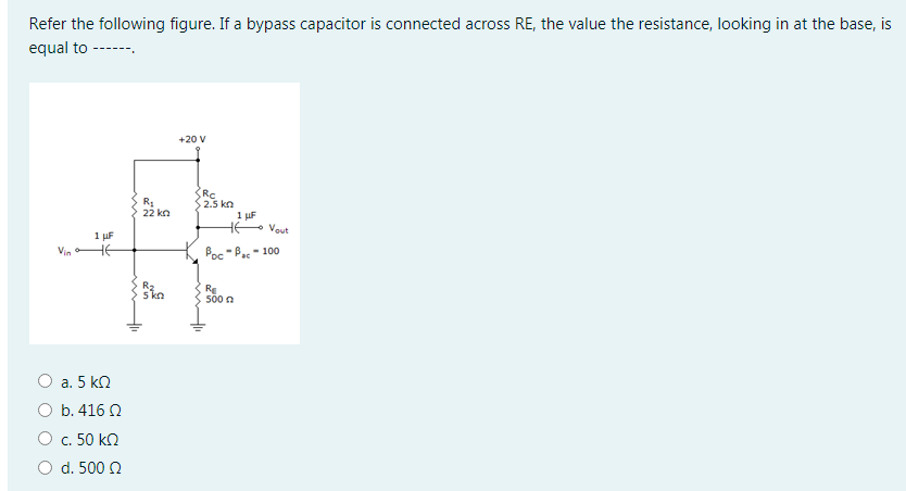
Step by step
Solved in 2 steps with 2 images
- You are working as an electrician in a large steel manufacturing plant, and you are in the process of doing preventive maintenance on a large DC generator. You have megged both the series and shunt field windings and found that each has over 10 M to ground. Your ohmmeter, however, indicates a resistance of 1.5 across terminals S1andS2. The ohmmeter indicates a resistance of 225 between terminals F1andF2. Are these readings normal for this type machine, or is there a likely problem? Explain your answer.Find the margin of K to keep the system shown in figure N°1 stableThe AC Bridge shown below is used to measure an unknown inductance, Lx and its internal resistance, Rx. The Bridge parameters are R1 = 20,000 ohms, R2 = 50,000 ohms, C2 = 0.003 μf, ω= 105 radians per sec. C1 is adjustable from 10 pf to 150 pf, and R3 is adjustable from 0 to 10,000 ohms. At Balance,I. Derive expressions for Rx and Lx in terms of ω, R1, R2, R3, C1, and C2.II. Determine the largest values of Rx and Lx that are measurable with the given parameters.
- 1) Use the superposition principle to determine the current in the load resistance RL, in the dc circuit of Figure QA1(a) 2) The current through a pure capacitor is given byi = 28.28cos(314t).Derive an expression for the voltage across the capacitor in the form v = Vm cos(wt) and comment on your answer. 3)Estimate the value of the current I and the voltage V in each of the circuits shown in Figure QA1(c) and justify your method of estimation.I NEED THIS ASAPPPP!!!!!!1 1.) For the circuit shown in Figure 3 with the output shown, determine the following parameters: Vcc = 44; VB = 20; VD =1.3; IH = 4.6mA; R = 10kΩ; Vmax Vmin Current in mA through the 10-kΩ resistor at t = to. Current in mA through the 10-kΩ resistor at t = t1. Current in mA through the 10-kΩ resistor at t = t2. Current in mA through the Shockley diode 1.) (a) ________ V(b) ________ V(c) ________mA(d) ________ mA(e) ________ mA(f) ________ mAIn the circuit given in the figure VT = 25mV, | VBE | = 0.7V, R1 = 712.91Kohm, R2 = 43.27Kohm, R3 = 2.29Kohm, R4 = 0.98Kohm, VCC = 10.00V, VEE = -4.00V, VA = 10.06V, Beta = 137.00, Rs = 38.43ohm, Ry Calculate the IC current according to = 16.55Kohm, Ri, R0 and the voltage gain (V0 / V1) according to the Source by full analysis When making your transactions, 2 steps will be taken after the point. Select the closest option according to +/- 10% margin of error. There is only one correct answer to the question.
- A 750-ohm resistor, an uncharged 1.50 uF capacitor, and a 8.00-V emf are connected in series. (a) What is the current after one time constant? (b) What is the voltage on the capacitor after one time constant?A coil of inductance 1 henry and negligible resistance is connected in series with a capacitancr of 10^-6 farad and an emf E volts. Taking Q=I=O at time t=0, find th3 charge Q anf the current I when t= 0.001 see if (a) E= 100 volts, (b) E= 100sin500t, (c) E= 100sin1000tQUESTION TEXT A potentiometer consisting of a wire of length = 10 cm has a source of emf, ɛ = 15V connected across it. When a standard cell with emf V = 6V, in series with a voltmeter, is connected at one end of the wire and at a distance L along the wire the voltmeter circuit is in balance and the voltmeter reads zero. What is the value of the balance length L? Select one: a. 1.5 cm b. 4.0 cm c. 6.0 cm d. 2.0 cm
- For circuit shown ini the pic. below, assuming VBE = 0.7 V.Determine: (a) IBQ(b) VB(c) ICQ(d) VE(e) VC(f) VCEQCan someone help with this task? Determine ?- inductive resistance- capacitive resistance- total resistance- total complex resistanceThe AC Bridge shown below is used to measure an unknown inductance, Lx and its internal resistance, Rx. The Bridge parameters are R1 = 20,000 ohms, R2 = 50,000 ohms, C2 = 0.003 µf, w = 105 radians per sec. C1 is adjustable from 10 pf to 150 pf, and R3 is adjustable from 0 to 10,000 ohms. At Balance, I. Derive expressions for Rx and Lx in terms of w, R1, R2, R3, C1, and C2. II. Determine the largest values of Rx and Lx that are measurable with the given parameters.