Referring to figure assume that the diameter of the rivet that joins the plates is d = 20 mm. The working stresses are 120 MPa for bearing in the plate and 60 MPa for shear in the rivet. Determine the minimum safe thickness of each plate.
Referring to figure assume that the diameter of the rivet that joins the plates is d = 20 mm. The working stresses are 120 MPa for bearing in the plate and 60 MPa for shear in the rivet. Determine the minimum safe thickness of each plate.

Mechanics of Materials (MindTap Course List)
9th Edition
ISBN:9781337093347
Author:Barry J. Goodno, James M. Gere
Publisher:Barry J. Goodno, James M. Gere
Chapter8: Applications Of Plane Stress (pressure Vessels, Beams, And Combined Loadings)
Section: Chapter Questions
Problem 8.3.1P: A fire extinguisher tank is designed for an internal pressure of 825 psi. The tank has an outer...

Related questions
Question
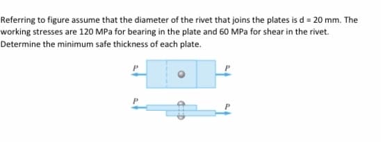
Transcribed Image Text:Referring to figure assume that the diameter of the rivet that joins the plates is d = 20 mm. The
working stresses are 120 MPa for bearing in the plate and 60 MPa for shear in the rivet.
Determine the minimum safe thickness of each plate.
Expert Solution
This question has been solved!
Explore an expertly crafted, step-by-step solution for a thorough understanding of key concepts.

This is a popular solution!

Trending now
This is a popular solution!

Step by step
Solved in 2 steps with 2 images

Knowledge Booster


Learn more about
Need a deep-dive on the concept behind this application? Look no further. Learn more about this topic, mechanical-engineering and related others by exploring similar questions and additional content below.Recommended textbooks for you
Mechanics of Materials (MindTap Course List)
Mechanical Engineering
ISBN:
9781337093347
Author:
Barry J. Goodno, James M. Gere
Publisher:
Cengage Learning
Mechanics of Materials (MindTap Course List)
Mechanical Engineering
ISBN:
9781337093347
Author:
Barry J. Goodno, James M. Gere
Publisher:
Cengage Learning