For the figure shown determine the value of the maximum normal stresses, due to the change of section and hole, if the radius is 15mm.
For the figure shown determine the value of the maximum normal stresses, due to the change of section and hole, if the radius is 15mm.

Mechanics of Materials (MindTap Course List)
9th Edition
ISBN:9781337093347
Author:Barry J. Goodno, James M. Gere
Publisher:Barry J. Goodno, James M. Gere
Chapter7: Analysis Of Stress And Strain
Section: Chapter Questions
Problem 7.3.11P: ‘7.3-11 The stresses on an element are sx= -300 psi and sy= 600 psi. Find the maximum shear stresses...

Related questions
Question
Can you help me to solve step by step
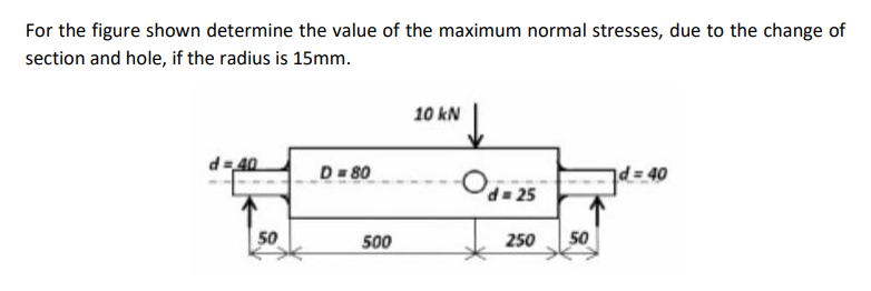
Transcribed Image Text:For the figure shown determine the value of the maximum normal stresses, due to the change of
section and hole, if the radius is 15mm.
10 kN
d=40
D =80
d=40
Od= 25
50
500
250
50
Expert Solution
This question has been solved!
Explore an expertly crafted, step-by-step solution for a thorough understanding of key concepts.

Step by step
Solved in 3 steps

Knowledge Booster


Learn more about
Need a deep-dive on the concept behind this application? Look no further. Learn more about this topic, mechanical-engineering and related others by exploring similar questions and additional content below.Recommended textbooks for you
Mechanics of Materials (MindTap Course List)
Mechanical Engineering
ISBN:
9781337093347
Author:
Barry J. Goodno, James M. Gere
Publisher:
Cengage Learning
Mechanics of Materials (MindTap Course List)
Mechanical Engineering
ISBN:
9781337093347
Author:
Barry J. Goodno, James M. Gere
Publisher:
Cengage Learning