
Structural Analysis
6th Edition
ISBN: 9781337630931
Author: KASSIMALI, Aslam.
Publisher: Cengage,
expand_more
expand_more
format_list_bulleted
Related questions
Concept explainers
Question
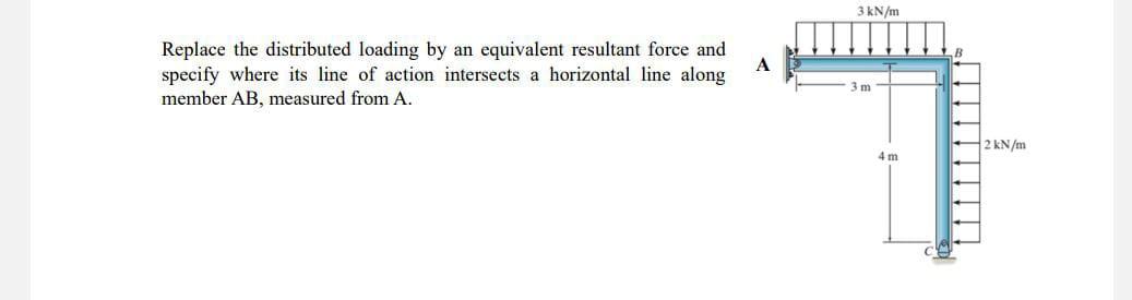

Transcribed Image Text:Replace the distributed loading by an equivalent resultant force and
specify where its line of action intersects a horizontal line along
member AB, measured from A.
A
3 kN/m
3 m
4m
2 kN/m
Expert Solution
This question has been solved!
Explore an expertly crafted, step-by-step solution for a thorough understanding of key concepts.

This is a popular solution

Trending nowThis is a popular solution!

Step by stepSolved in 4 steps with 2 images

Knowledge Booster


Learn more about
Need a deep-dive on the concept behind this application? Look no further. Learn more about this topic, civil-engineering and related others by exploring similar questions and additional content below.Similar questions
- Consider the beam and loading shown. Given, M = 1.5 kip·ft. Identify the correct shear diagram and determine the maximum absolute value of the shear.arrow_forwardCan you please solve these three questions?arrow_forwardDEFLECTION OF BEAM BY AREA-MOMENT METHOD PLATE #3 C 10 KN 0.60m 0.60m 17.55 33.80 K E 6.30m 10 KN 0.75m 0.75m 17.55 KN 1.20m 1. Draw the shear and moment diagram and label their corresponding values. 2. Find the deflection at the point of zero shear. Use E= 200,000 MPa 1.50m I 1,034 x 10^6 mm^4 Farrow_forward
- 3. The cross section of a weightless quarter circular gate AB of width 0.9 m is shown in Figure 3.The hinge is along AA. Calculate the force R at B to hold the gate in this position.arrow_forwardIn the system shown in the figure, parts AB, BC and CD are of equal length and 4 m. Clockwise from point AA moment of 10 kNm is applied in the opposite direction. The distributed load of 3 kN/m at BC is upward. Beam DA load of 5 kN was applied downwards from the point. The profile of the beam has a 100 mm edge as seen on the right side.was formed by subtracting a circle with a diameter of 80 mm from the center of a regular hexagon of length. Accordingly; A)Calculate the reaction forces at B and C B)Draw shear force and bending moment diagrams C)Calculate the maximum bending and show it on the bending moment diagram. D)Calculate the sectional moment of inertia of the profile E)Calculate the maximum stress in the beam NOTE:For option C, you need to obtain a parobolic expression when drawing the bending moment diagram. You need to use derivation.arrow_forward
arrow_back_ios
arrow_forward_ios
Recommended textbooks for you
 Structural Analysis (10th Edition)Civil EngineeringISBN:9780134610672Author:Russell C. HibbelerPublisher:PEARSON
 Principles of Foundation Engineering (MindTap Cou...Civil EngineeringISBN:9781337705028Author:Braja M. Das, Nagaratnam SivakuganPublisher:Cengage Learning
 Fundamentals of Structural AnalysisCivil EngineeringISBN:9780073398006Author:Kenneth M. Leet Emeritus, Chia-Ming Uang, Joel LanningPublisher:McGraw-Hill Education
 Traffic and Highway EngineeringCivil EngineeringISBN:9781305156241Author:Garber, Nicholas J.Publisher:Cengage Learning
Structural Analysis (10th Edition)
Civil Engineering
ISBN:9780134610672
Author:Russell C. Hibbeler
Publisher:PEARSON
Principles of Foundation Engineering (MindTap Cou...
Civil Engineering
ISBN:9781337705028
Author:Braja M. Das, Nagaratnam Sivakugan
Publisher:Cengage Learning
Fundamentals of Structural Analysis
Civil Engineering
ISBN:9780073398006
Author:Kenneth M. Leet Emeritus, Chia-Ming Uang, Joel Lanning
Publisher:McGraw-Hill Education
Traffic and Highway Engineering
Civil Engineering
ISBN:9781305156241
Author:Garber, Nicholas J.
Publisher:Cengage Learning