The average output voltage, Vo of an ideal full wave rectifier is 9.55 V and its output voltage frequency is 100 Hz. (i) Determine the peak value of the input voltage, v,, assuming it is a sine wave. Sketch the input signal v, and output signal v, on a common time axis labelling clearly the magnitude and time. (i)
The average output voltage, Vo of an ideal full wave rectifier is 9.55 V and its output voltage frequency is 100 Hz. (i) Determine the peak value of the input voltage, v,, assuming it is a sine wave. Sketch the input signal v, and output signal v, on a common time axis labelling clearly the magnitude and time. (i)

Electricity for Refrigeration, Heating, and Air Conditioning (MindTap Course List)
10th Edition
ISBN:9781337399128
Author:Russell E. Smith
Publisher:Russell E. Smith
Chapter12: Electronic Control Devices
Section: Chapter Questions
Problem 4RQ: What is the difference between a diode and rectifier?

Related questions
Question
M:06)
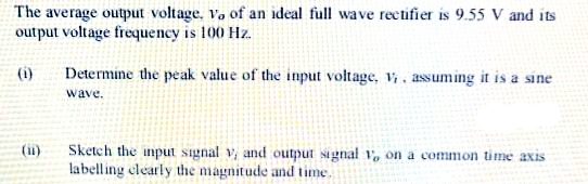
Transcribed Image Text:The average output voltage, Vo of an ideal full wave rectifier is 9.55 V and its
output voltage frequency is 100 Hz.
(i)
Determine the peak value of the input voltage, v, assuming it is a sine
wave.
Sketch the input signal v and output signal 1, on a common time axis
labelling clearly the magnitude and time.
(ii)
Expert Solution
This question has been solved!
Explore an expertly crafted, step-by-step solution for a thorough understanding of key concepts.

This is a popular solution!

Trending now
This is a popular solution!

Step by step
Solved in 2 steps with 2 images

Knowledge Booster


Learn more about
Need a deep-dive on the concept behind this application? Look no further. Learn more about this topic, electrical-engineering and related others by exploring similar questions and additional content below.Recommended textbooks for you
Electricity for Refrigeration, Heating, and Air C…
Mechanical Engineering
ISBN:
9781337399128
Author:
Russell E. Smith
Publisher:
Cengage Learning
Electricity for Refrigeration, Heating, and Air C…
Mechanical Engineering
ISBN:
9781337399128
Author:
Russell E. Smith
Publisher:
Cengage Learning