The beam ABCD with a rectangular cross section carries the loading shown in the figure. Determine the maximum bending stress in the beam in MPa. 2 kN 50 mm 5 kN • m D 80 mm +1.0 m E1.0 m –1.0 m - O 25 O 100 O 50 O 75
The beam ABCD with a rectangular cross section carries the loading shown in the figure. Determine the maximum bending stress in the beam in MPa. 2 kN 50 mm 5 kN • m D 80 mm +1.0 m E1.0 m –1.0 m - O 25 O 100 O 50 O 75

Mechanics of Materials (MindTap Course List)
9th Edition
ISBN:9781337093347
Author:Barry J. Goodno, James M. Gere
Publisher:Barry J. Goodno, James M. Gere
Chapter9: Deflections Of Beams
Section: Chapter Questions
Problem 9.10.6P: An overhanging beam ABC with a rectangular cross section has the dimensions shown in the figure. A...

Related questions
Question
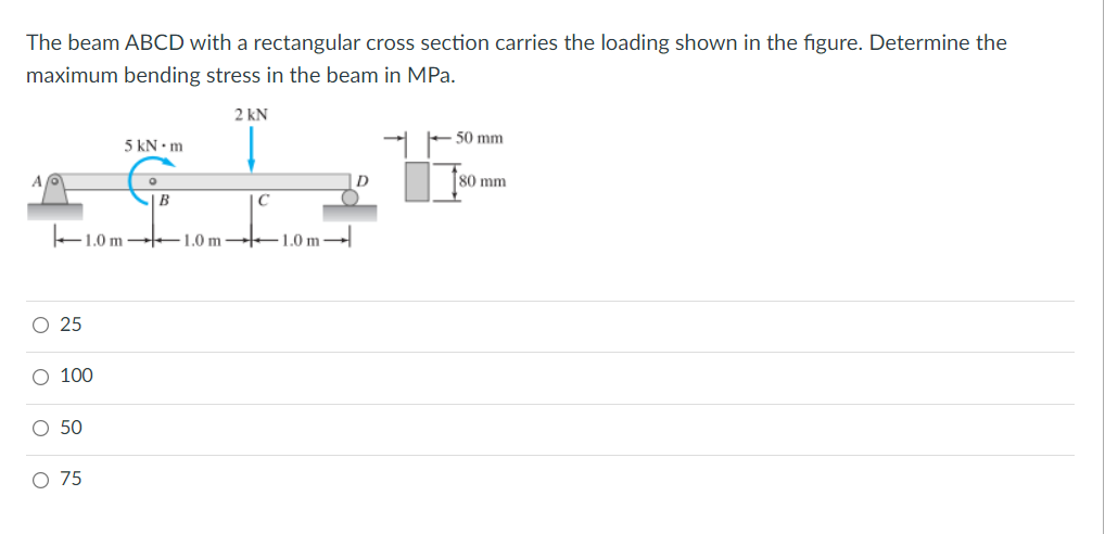
Transcribed Image Text:The beam ABCD with a rectangular cross section carries the loading shown in the figure. Determine the
maximum bending stress in the beam in MPa.
2 kN
50 mm
5 kN • m
D
80 mm
+1.0 m E1.0 m –1.0 m -
O 25
O 100
O 50
O 75
Expert Solution
This question has been solved!
Explore an expertly crafted, step-by-step solution for a thorough understanding of key concepts.

Step by step
Solved in 2 steps with 2 images

Knowledge Booster


Learn more about
Need a deep-dive on the concept behind this application? Look no further. Learn more about this topic, mechanical-engineering and related others by exploring similar questions and additional content below.Recommended textbooks for you
Mechanics of Materials (MindTap Course List)
Mechanical Engineering
ISBN:
9781337093347
Author:
Barry J. Goodno, James M. Gere
Publisher:
Cengage Learning
Mechanics of Materials (MindTap Course List)
Mechanical Engineering
ISBN:
9781337093347
Author:
Barry J. Goodno, James M. Gere
Publisher:
Cengage Learning