H.W.3 /The simply supported beam in Figure below has a rectangular cross section with dimension (30 mm(width) x50 mm (height)) . If the allowable bending stress is 5 MPa. a- Determine the concentrated load (P). (b)Sketch the bending stress distribution over the cross section on which the maximum bending stress occurs. P kN A -4 M 4 M
H.W.3 /The simply supported beam in Figure below has a rectangular cross section with dimension (30 mm(width) x50 mm (height)) . If the allowable bending stress is 5 MPa. a- Determine the concentrated load (P). (b)Sketch the bending stress distribution over the cross section on which the maximum bending stress occurs. P kN A -4 M 4 M

Mechanics of Materials (MindTap Course List)
9th Edition
ISBN:9781337093347
Author:Barry J. Goodno, James M. Gere
Publisher:Barry J. Goodno, James M. Gere
Chapter5: Stresses In Beams (basic Topics)
Section: Chapter Questions
Problem 5.13.3P: A rectangular beam with semicircular notches, as shown in part b of the figure, has dimensions h =...

Related questions
Question
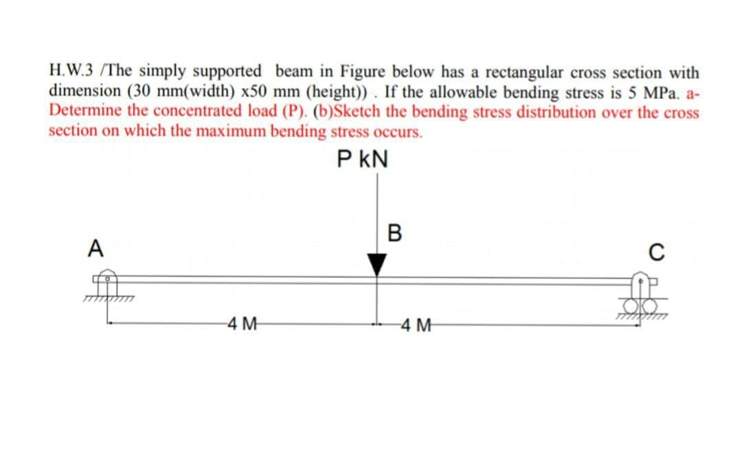
Transcribed Image Text:H.W.3 /The simply supported beam in Figure below has a rectangular cross section with
dimension (30 mm(width) x50 mm (height)). If the allowable bending stress is 5 MPa. a-
Determine the concentrated load (P). (b)Šketch the bending stress distribution over the cross
section on which the maximum bending stress occurs.
P kN
В
A
C
4 M
4 M
Expert Solution
This question has been solved!
Explore an expertly crafted, step-by-step solution for a thorough understanding of key concepts.

Step by step
Solved in 3 steps with 3 images

Knowledge Booster


Learn more about
Need a deep-dive on the concept behind this application? Look no further. Learn more about this topic, mechanical-engineering and related others by exploring similar questions and additional content below.Recommended textbooks for you
Mechanics of Materials (MindTap Course List)
Mechanical Engineering
ISBN:
9781337093347
Author:
Barry J. Goodno, James M. Gere
Publisher:
Cengage Learning
Mechanics of Materials (MindTap Course List)
Mechanical Engineering
ISBN:
9781337093347
Author:
Barry J. Goodno, James M. Gere
Publisher:
Cengage Learning