The rigid bar A,B,C,D shown in figure is connected to the ground by a hinge at B and to Magnesium bar at A, Aluminum bar at C. the properties of the bars are shown on the figure. all the connections are using 16 mm bolts in single shear. Determine the maximum safe load W that can be applied. Determine the final position of point D.
The rigid bar A,B,C,D shown in figure is connected to the ground by a hinge at B and to Magnesium bar at A, Aluminum bar at C. the properties of the bars are shown on the figure. all the connections are using 16 mm bolts in single shear. Determine the maximum safe load W that can be applied. Determine the final position of point D.

Mechanics of Materials (MindTap Course List)
9th Edition
ISBN:9781337093347
Author:Barry J. Goodno, James M. Gere
Publisher:Barry J. Goodno, James M. Gere
Chapter8: Applications Of Plane Stress (pressure Vessels, Beams, And Combined Loadings)
Section: Chapter Questions
Problem 8.3.3P: A scuba t a n k (see fig ure) i s bci ng d e signed fo r an internal pressure of 2640 psi with a...

Related questions
Question
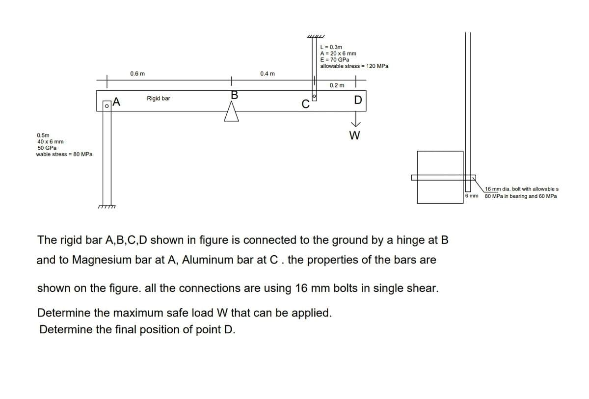
Transcribed Image Text:L = 0.3m
A = 20 x 6 mm
E = 70 GPa
allowable stress = 120 MPa
0.6 m
0.4 m
0.2 m
B
Rigid bar
A
C
W
0.5m
40 x 6 mm
50 GPa
wable stress = 80 MPa
16 mm dia. bolt with allowables
6 mm
80 MPa in bearing and 60 MPa
The rigid bar A,B,C,D shown in figure is connected to the ground by a hinge at B
and to Magnesium bar at A, Aluminum bar at C. the properties of the bars are
shown on the figure. all the connections are using 16 mm bolts in single shear.
Determine the maximum safe load W that can be applied.
Determine the final position of point D.
Expert Solution
This question has been solved!
Explore an expertly crafted, step-by-step solution for a thorough understanding of key concepts.

Step by step
Solved in 7 steps with 10 images

Knowledge Booster


Learn more about
Need a deep-dive on the concept behind this application? Look no further. Learn more about this topic, mechanical-engineering and related others by exploring similar questions and additional content below.Recommended textbooks for you
Mechanics of Materials (MindTap Course List)
Mechanical Engineering
ISBN:
9781337093347
Author:
Barry J. Goodno, James M. Gere
Publisher:
Cengage Learning
Mechanics of Materials (MindTap Course List)
Mechanical Engineering
ISBN:
9781337093347
Author:
Barry J. Goodno, James M. Gere
Publisher:
Cengage Learning