The three-phase power and line-line ratings of the electric power system shown in Figure-1 are given below: G,:(first and Last digit of SAP ID) MVA T:(G,rating-10) MVA T:(G,rating -10) MVA M:((T,rating-10)) MVA Line: 30 kV X=10% 30/300 kV X=11% 300/30 kV X=11% 25 kV X=9% 30 kV Z-First two digits of SAP ID + j (2x first two digits of SAP ID) T2 Vm Line 2 G M Figure 1 Apply the knowledge of per unit system on above network and draw an impedance diagram showing all impedances in per unit when S, = 100 MVA and V, = 30 kV
The three-phase power and line-line ratings of the electric power system shown in Figure-1 are given below: G,:(first and Last digit of SAP ID) MVA T:(G,rating-10) MVA T:(G,rating -10) MVA M:((T,rating-10)) MVA Line: 30 kV X=10% 30/300 kV X=11% 300/30 kV X=11% 25 kV X=9% 30 kV Z-First two digits of SAP ID + j (2x first two digits of SAP ID) T2 Vm Line 2 G M Figure 1 Apply the knowledge of per unit system on above network and draw an impedance diagram showing all impedances in per unit when S, = 100 MVA and V, = 30 kV

Power System Analysis and Design (MindTap Course List)
6th Edition
ISBN:9781305632134
Author:J. Duncan Glover, Thomas Overbye, Mulukutla S. Sarma
Publisher:J. Duncan Glover, Thomas Overbye, Mulukutla S. Sarma
Chapter3: Power Transformers
Section: Chapter Questions
Problem 3.25P: Consider a single-phase electric system shown in Figure 3.33. Transformers are rated as follows:...

Related questions
Question
SAP ID =8925
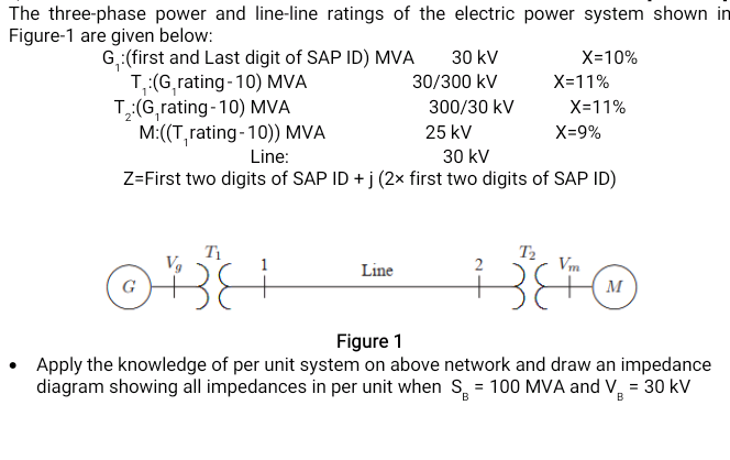
Transcribed Image Text:The three-phase power and line-line ratings of the electric power system shown in
Figure-1 are given below:
G,:(first and Last digit of SAP ID) MVA
T:(G,rating-10) MVA
T(G,rating-10) MVA
M:((T,rating-10)) MVA
30 kV
X=10%
30/300 kV
X=11%
300/30 kV
X=11%
25 kV
X=9%
Line:
30 kV
Z=First two digits of SAP ID + j (2× first two digits of SAP ID)
T1
T2
Vm
Line
2
G
M
Figure 1
• Apply the knowledge of per unit system on above network and draw an impedance
diagram showing all impedances in per unit when S, = 100 MVA and V, = 30 kV
Expert Solution
This question has been solved!
Explore an expertly crafted, step-by-step solution for a thorough understanding of key concepts.

Step by step
Solved in 3 steps with 1 images

Knowledge Booster


Learn more about
Need a deep-dive on the concept behind this application? Look no further. Learn more about this topic, electrical-engineering and related others by exploring similar questions and additional content below.Recommended textbooks for you
Power System Analysis and Design (MindTap Course …
Electrical Engineering
ISBN:
9781305632134
Author:
J. Duncan Glover, Thomas Overbye, Mulukutla S. Sarma
Publisher:
Cengage Learning
Power System Analysis and Design (MindTap Course …
Electrical Engineering
ISBN:
9781305632134
Author:
J. Duncan Glover, Thomas Overbye, Mulukutla S. Sarma
Publisher:
Cengage Learning