Q2. The one-line diagram of a simple power system is shown below. The load, to be represented as an impedance, draws 90 MW at 6.9 kV and 0.8 power factor lagging. The generators and transformers are rated as follows : : 60 MVA , 13.2 kV , X"= 0.2 pu Generator 2 : 30 MVA , 6.9 kV , X"=0.15 pu Transformer 1: 30 MVA , 13.8A / 120 Y kV, X= 0.2 pu Transformer 2: 40 MVA , 120 Y / 6.9 Y kV , X=0.1 pu Generator 1 : (a) Draw the impedance diagram and indicate all impedances in pu. Choose a base of 40VA, 13.8 kV in Generator 1 circuit. (b) Find Generator 2 internal emf E2 if the internal emf of Generator 1 is E1 = 1.1Z 0° pu and the load voltage is VL =1.0Z 0° pu. Specify magnitude of E2 in pu and in kV.
Q2. The one-line diagram of a simple power system is shown below. The load, to be represented as an impedance, draws 90 MW at 6.9 kV and 0.8 power factor lagging. The generators and transformers are rated as follows : : 60 MVA , 13.2 kV , X"= 0.2 pu Generator 2 : 30 MVA , 6.9 kV , X"=0.15 pu Transformer 1: 30 MVA , 13.8A / 120 Y kV, X= 0.2 pu Transformer 2: 40 MVA , 120 Y / 6.9 Y kV , X=0.1 pu Generator 1 : (a) Draw the impedance diagram and indicate all impedances in pu. Choose a base of 40VA, 13.8 kV in Generator 1 circuit. (b) Find Generator 2 internal emf E2 if the internal emf of Generator 1 is E1 = 1.1Z 0° pu and the load voltage is VL =1.0Z 0° pu. Specify magnitude of E2 in pu and in kV.

Power System Analysis and Design (MindTap Course List)
6th Edition
ISBN:9781305632134
Author:J. Duncan Glover, Thomas Overbye, Mulukutla S. Sarma
Publisher:J. Duncan Glover, Thomas Overbye, Mulukutla S. Sarma
Chapter3: Power Transformers
Section: Chapter Questions
Problem 3.41P: Consider the single-line diagram of the power system shown in Figure 3.38. Equipment ratings are...

Related questions
Question
Electrical Engineering - Power System Analysis Please solve the question step by step
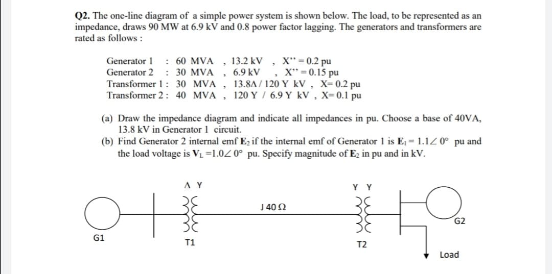
Transcribed Image Text:Q2. The one-line diagram of a simple power system is shown below. The load, to be represented as an
impedance, draws 90 MW at 6.9 kV and 0.8 power factor lagging. The generators and transformers are
rated as follows :
, 13.2 kV
6.9 kV
Transformer 1: 30 MVA , 13.8A/ 120 Y kV , X= 0.2 pu
Transformer 2 : 40 MVA , 120 Y / 6.9 Y kV , X=0.1 pu
: 60 MVA
: 30 MVA
X" = 0.2 pu
X" = 0.15 pu
Generator 1
Generator 2
(a) Draw the impedance diagram and indicate all impedances in pu. Choose a base of 40VA,
13.8 kV in Generator 1 circuit.
(b) Find Generator 2 internal emf Ez if the internal emf of Generator 1 is Ej = 1.1Z 0° pu and
the load voltage is VL =1.0Z 0° pu. Specify magnitude of E2 in pu and in kV.
ΔΥ
Y Y
J40 Ω
G2
G1
T1
T2
Load
Expert Solution
This question has been solved!
Explore an expertly crafted, step-by-step solution for a thorough understanding of key concepts.

Step by step
Solved in 3 steps with 2 images

Knowledge Booster


Learn more about
Need a deep-dive on the concept behind this application? Look no further. Learn more about this topic, electrical-engineering and related others by exploring similar questions and additional content below.Recommended textbooks for you
Power System Analysis and Design (MindTap Course …
Electrical Engineering
ISBN:
9781305632134
Author:
J. Duncan Glover, Thomas Overbye, Mulukutla S. Sarma
Publisher:
Cengage Learning
Power System Analysis and Design (MindTap Course …
Electrical Engineering
ISBN:
9781305632134
Author:
J. Duncan Glover, Thomas Overbye, Mulukutla S. Sarma
Publisher:
Cengage Learning