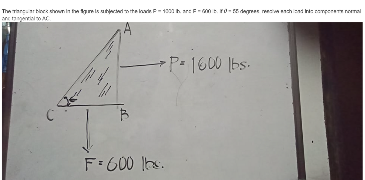
The triangular block shown in the figure is subjected to the loads P = 1600 lb. and F = 600 lb. If 0 = 55 degrees, resolve each load into compon and tangential to AC.


Q: Find the load of the system of convergent forces acting on the body AL in 400N the figure (3) k2m.
A:
Q: The triangular block shown in the figure below is subjected to the loads P= 360 N and F = 130 N. If…
A: Consider the diagram shown below.
Q: The cantilever truss in the figure is hinged at D and E. Find the force in member AC. 1000 Ib 60 60•…
A:
Q: The assembly in the given figure is consists of steel and aluminium bars and it is fixed at the wall…
A:
Q: Assume the plate shown in Figure has negligible weight. There is a ball and socket joint at A and a…
A:
Q: 100 kN 1.5 10 kN/m 1.5
A: given:
Q: W.S. 2.50 m A 1.50 m B
A:
Q: The system with two pin supports, and having an internal pin at C, is subject to two horizontal…
A:
Q: In the figure, one end of a uniform beam of weight 480 N is hinged to a wall; the other end is…
A:
Q: For the bracket shown in the figure: > The moment of the force (1000N) about pin A is.... > The…
A:
Q: 40 2. In the figure at center right, each cable can support a maximum of 250 lb of tension. Find the…
A:
Q: The figure shows the cross section of three cylinders, 1m long, given the density of steel 500…
A: The reaction acting on the system is shown below. The angles are determined as follows. α=cos-1100…
Q: 6.) The system of knotted cords shown in the figure supports the indicated weights. Compute the…
A:
Q: A simple truss is subjected to 20 kN force at point A as shown in Figure 2. The reaction force at…
A:
Q: Figure Q2 shows a shaft consists of Rods AB, BC and CD which made of Aluminium, Brass and Steel,…
A:
Q: Figure 6: 5 m/ 5 m 5 m B 20 KN A simple truss is subjected to 20 KN force at the point A as shown in…
A: The reaction force at point C is 20 kN (Tension). Therefore, option (b) is correct answer.
Q: 4-13. A vertical square gate separates two compartments of a pressurized air tank, as shown in…
A:
Q: Question 2: The cross-sectional area for the lattice rods in the figure is A=120 mm2, the modulus of…
A: Solution
Q: In the figure below, all the bearings are movable bearings and the C bearing is in an inclined…
A:
Q: The two bearings (B1) and (B2) are used to support a shaft as shown in the figure Using the data…
A:
Q: + The forces are given in figure and applied as shown. 3 F,-100 KN Fq= 50KN and F3= 30 KN. The…
A: The main difference between twisting moment and bending moment is that their directions of moment.…
Q: ka 2 ki P Rigid bar k3 for the system shown in the figure, which of the following statements are…
A: from the figure , we see that , point 1,2,3,4 are rigid on the wall , so they can't move while…
Q: The figure below shows a symmetric T-section that is subjected to a linearly varying distributed…
A: In this problem, it is asking about the equivalent force of the given distributed load.
Q: 8. Refer to figure 9. Given the following information: angles 0r= 20°, 02= 30°, 03= 41°, a 200 N…
A:
Q: A plane truss is shown in the figure. a = 4 m, b = 13 m, F = 18 kN. F2 = 28 kN. Find forces in the…
A:
Q: The vertical reaction in the hinged support shown in the figure is Blank 1 N.
A:
Q: Two cables are tied together at C and loaded as shown in the figure. If the weight of the load is 10…
A:
Q: Figure Q2 shows a shaft consists of Rods AB, BC and CD which made of Aluminium, Brass and Steel,…
A:
Q: The solid rod shown in the figure below has radius of 0.63 in. If it is subjected to the force of…
A:
Q: In the structure shown in below figure, the member which carries zero force, is a a 450 2 kN ВЕ AB O…
A:
Q: In the figure, one end of a uniform beam of weight 130 N is hinged to a wall; the other end is…
A:
Q: bent bar shown in figure is supported at A with a ball-and-sc a cable and a link, and the support at…
A:
Q: For the frame shown in figure below, the rotation at (A) equals:
A:
Q: 2. The structure is connected by a pin joint at point A and by a cable of length L at points B and…
A: The free-body diagram of the above structure is given as, Apply force equilibrium in the vertical…
Q: Problem Number 2: A horizontal boom 11.5 M in length, AE is supported by guy wires from A to B,C and…
A:
Q: The frame shown in Figure below consists of two members (BC and ABD) and it is subjected by the…
A:
Q: In the system in the figure, two rods carry the P force. a) Since the maximum stress that the rods…
A:
Q: Given the loading criteria in the figure below, find all reaction forces. |80 kN 30 kN/m 2m 3m 2m
A: A uniformly distributed load (UDL) is a load that is evenly distributed throughout the whole…
Q: A 100N load is supported by a strong bar as shown in the figure. The tension in the cable is 200N.…
A:
Q: A rod is attached to a pivot on the wall at one end and suspended horizontally at the other end by a…
A: Given: Suspended mass (m)=1kgMass of the rod (M)=2kgLength of the rod (L)=4m
Q: What are the magnitude (F) and the location measured from end A (d) of the equivalent resultant…
A:
Q: D A AB Ac 03 B Torre de soporte WB Wc L= 100 ft
A:
Q: For the cables shown in the figure, find the forces in each cable if cable C pass over a pulley and…
A: The weight of the holding mass is as follows: W=mgW=10×9.81W=98.1 N The tension in the cable D will…
Q: Q1) 28 N.m torque is needed to turn the bolt around its axis as shown in the Figure (1) below. Find…
A:
Q: Now, if the end of the bar marked by the red circle in the figure below is the only spot where you…
A: There are three types of loading 1. Point load 2. UDL 3. UVL Point load is the simplest form and it…
Q: The cantilever truss in the figure is hinged at D and E. Find the force in member DC. 1000 Ib 60 60…
A:
Q: A simple truss is subjected to 20 kN force at point A as shown in Figure 2. The reaction force at…
A:
Q: 1: An overhead transmission line conductor at river having two un same level towers the eight of…
A: Given- Height of tall tower = 75m Horizontal Distance = 200m Minimum clearance =22.1875m Weight of…
Q: ven m-50kg and the following dimensions: AB = 1m, BC 3m, angle ACD 30 degrees Draw a free body…
A:
Complete Solution


Trending now
This is a popular solution!

Step by step
Solved in 2 steps with 2 images

- A plane frame with a pin support at A and roller supports at C and £ has a cable attached at E. which runs over Frictionless pulleys al D and B (see figure). The cable force is known to be 400 N. There is a pin connection just Lo the left of joint C. (a) Find reactions at supports^, C, and E. (b) Find internal stress, resultants N, V, and M just to the right of joint C. (c) Find resultant force in the pin near C..15 A hitch-mounted bicycle rack is designed to carry up to four 30-lb bikes mounted on and strapped to two arms Gil (sec bike loads in the figure part a) The rack is attached to the vehicle at A and is assumed to be like a cant silkier beam A BCDGII (figure part b) The light of fixed segment AB is U = 10 lb. centered 9 in. from A (see figure part b) and the rest of the rack highs W2 = 40 lb. centered 19 in. from A. Segment ABCDG is a steel tube o(2 X 2 in. with a thickness I = 118 in. Segment BCDGII pivots about a bolt at B with a diameter d1 = 0.25 in. to allow access to the rear of the vehicle without removing the hitch rack. When in use, the rack is secured in an upright posit ion by a pin C(diameter o( pin d, = 5116 in.) (see phoo and figure part C). The of returning effect of the bikes on the rack is resisted by a force couple F h at BC. (a) Find the support reactions at A for the fully loaded rack. (b) Find forces in the bolt at B and the pin at C. (c) Find average shear stresses in both the bolt at Band the pin at C. (d) Find average bearing stresses o, in the bolt at B and the pin at C.The main cables of a suspension bridge (see figure part a) follow a curve that is nearly parabolic because the primary load on the cables is the weight of the bridge deck, which is uniform in intensity along the horizontal. Therefore, represent the central region AOB of one of the main cables (see part b of the figure) as a parabolic cable supported at points A and B and carrying a uniform load of intensity q along the horizontal. The span of the cable is L, the sag is /i, the axial rigidity is EA\ and the origin of coordinates is at mid span. (a) Derive the following formula for the elongation of cable AOB shown in part b or the figure: (b) Calculate the elongation 5 of the central span of one of the main cables of the Golden Gate Bridge for which the dimensions and properties are L = 4200 ft,h = 470 ft, q = 12,700 lb/ft, and E = 23,300,000 psi The cable consists of 27,572 parallel wires of diameter 0.196 in. Hint: Determine the tensile force Tal any point in the cable from a free-body diagram of part of the cable; then determine the elongation of an element of the cable of length ds: finally, integrate along the curve of the cable to obtain an equation for the elongation £.
- Two separate cables AC and BC support a sign structure of weight W = 1575 lb attached to a building. The sign is also supported by a pin support at O and a lateral restraint in the '-direction at D. (a) Find the tension in each cable. Neglect the mass of the cables. (b) Find the average stress in each cable if the area of each cable is Ae= 0.471 in2.A 150-lb rigid bar AB. with friction less rollers al each end. is held in the position shown in the figure by a continuous cable CAD. The cable is pinned at C and D and runs over a pulley at A. (a) Find reactions at supports A and B. (b) Find the force in the cable.Solve the preceding problem for the following data: b = 8.0 in., k = 16 lb/in., a = 45°, and P = 10 lb.
- A long re Lai nine: wall is braced by wood shores set at an angle of 30° and supported by concrete thrust blocks, as shown in the first part of the figure. The shores are evenly spaced at 3 m apart. For analysis purposes, the wall and shores are idealized as shown in the second part of the figure. Note that the base of the wall and both ends of the shores are assumed to be pinned. The pressure of the soil against the wall is assumed to be triangularly distributed, and the resultant force acting on a 3-meter length of the walls is F = 190 kN. If each shore has a 150 mm X 150 mm square cross section, what is the compressive stressRepeat Problem 2.3-29 if vertical load P at D is replaced by a horizontal load P at D (see figure).A mountain bike is moving along a flat path at constant velocity. At some instant, the rider (weight = 670 N) applies pedal and hand forces, as shown in the figure part a. (a) Find reaction forces at the front and rear hubs. (Assume that the bike is pin supported at the rear hub and roller supported at the front hub.) (b) Find internal stress resultants N, V, and M in the inclined seat post (see figure part b
- A plane Frame with pin supports at A and E has a cable attached at C, which runs over a friction-less pulley at F(see figure). The cable Force is known to be 500 lb. (a) Find reactions at supports A and E. (b) Find internal stress resultants N, V, and M at point H.A space truss is restrained at joints O, A. B. and C, as shown in the figure. Load P is applied at joint A and load IP acts downward at joint C. (a) Find reaction force components Ax, By, and B. in terms of load variable P. (b) Find the axial force in truss member AB in terms of load variable P.A crane boom of mass 450 leg with its center of mass at C is stabilized by two cables AQ and BQ (Ae= 304 mm2 for each cable) as shown in the figure. A load P = 20 KN is supported at point D. The crane boom lies in the y-z plane. (a) Find the tension forces in each cable: TAQand TBQ(kN}. Neglect the mass of the cables, but include the mass of the boom in addition to load P. (b) Find the average stress (s) in each cable.