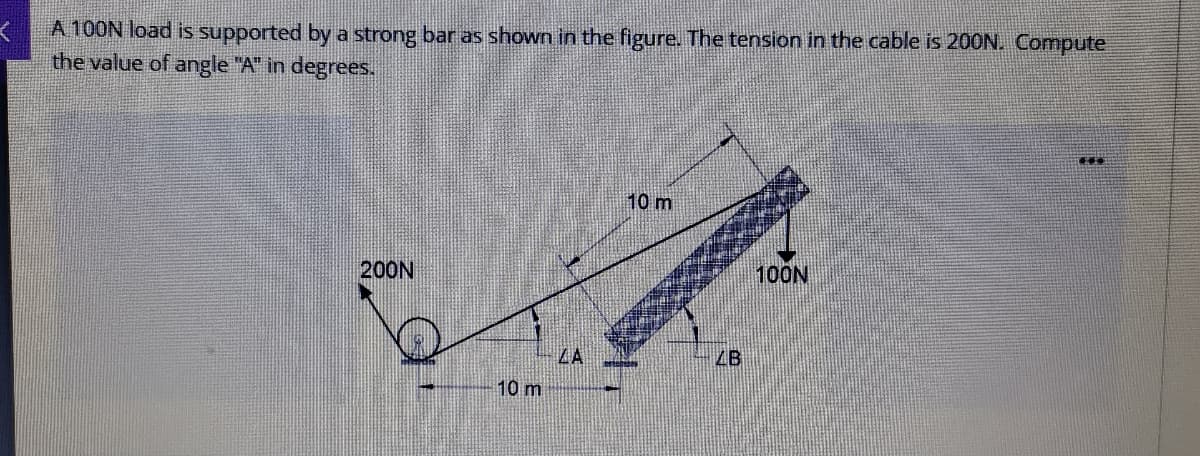
A 100N load is supported by a strong bar as shown in the figure. The tension in the cable is 200N. Compute the value of angle "A" in degrees.


Q: A uniformly distributed force of C kN/m and a concentrated load of D kN are applied to a cantilever…
A:
Q: A steel bar of cross-sectional area 200 mm^2 is loaded as shown in Fig. Find the change in length of…
A: For solution refer below images.
Q: Anchor of the beam given in the figure is built-in support, B point is movable support and G joint.…
A: Let the reactions at fixed support 'A' be: RAH , RAV , MA. Let the reactions at pin joint 'G' be:…
Q: Consider the frame shown in Fig 4. A 100N load is suspended around a fixed drum with radius 2 m…
A:
Q: Consider the truss shown in (Figure 1). Suppose that F = 60 kN and F2 = 30 kN. !! Figure < 1 of 1 50…
A:
Q: The load W is to be lifted using the crane shown in the figure, neglect the weight of the crane.…
A: We are authorized to answer one question at a time since you have not mentioned which question you…
Q: Q: A rigid block of negligible mass is supported by three rods as shown in figure, if a load (P) is…
A:
Q: The cable and boom shown in the figure support a load of 600 lb. Determine the tensile force, T, in…
A:
Q: For the figure shown, have the following information: Bar (1) made of bronze Bar (2) made of…
A:
Q: Two loads 400N and 500N are suspended in a vertical plane by three springs as shown in Figure. Find…
A:
Q: A 7.5kg sign is hung off of the end of a 3.7kg metal arm as shown in the figure. (Note that while…
A: Given Data: The mass of the arm is m1=3.7 kg. The mass of the sign is m2 = 7.5 kg. The center of…
Q: In the figure, one end of a uniform beam of weight 440 N is hinged to a wall; the other end is…
A: Consider the FBD as shown below.
Q: 3. The figure shows a frame supported by pins at A and D and carries a triangular load of maximum…
A: In the given example, member DCB will exert a compressive force at point B. We will consider FBDs of…
Q: In the figure, one end of a uniform beam of weight 410 N is hinged to a wall; the other end is…
A: ...
Q: For the truss shown in figure (3), find the forces in member (BC, HG, CG, and DF) and state whether…
A:
Q: A force of 100 lb is applied to the frame shown (See the Figure below). Calculate the load in member…
A:
Q: The 1.5 kN vertical OA pole is supported as shown in the figure and loaded with a horizontal force…
A: Given: The weight of the pole is 1.5 kN. The pole with the supported load is shown below:
Q: A uniform steel bar of length 10 m is supported at point A and B using two cables as shown in the…
A:
Q: In the figure, one end of a uniform beam of weight 340 N is hinged to a wall; the other end is…
A:
Q: Q2/ A steel bar shown in figure consists of two segments having diameter of AB= 28 mm and BD= 40 mm.…
A:
Q: A steel tube is rigidly attached between an aluminum rod and a bronze rod as shown in the figure.…
A:
Q: Question 2: The cross-sectional area for the lattice rods in the figure is A=120 mm2, the modulus of…
A: Solution
Q: Rod AB is fixed to a smooth collar D, which slides freely along the vertical guide shown in (Figure…
A: Given:- P=65lb w=16lb/ft To find:- a) Nc b) Vc c) Mc
Q: For the overhanging truss shown in figure below, compute the member forces in BC, CE and DE. 5kN 3m…
A: Given:- Overhanging truss To Determine:- Forces in members BC, CE and DE.
Q: (4) The Jib crane shown in figure carries load of W. If the maximum load in the tie is 25 kN,…
A: Given ,
Q: For the truss shown in Figure The cross sectional area of each member is 1000 mm² Find the stresses…
A:
Q: Example: Body M shown in figure weighs (300 N) and the homogeneous bar BE weighs (60 N). Draw the…
A:
Q: Two cables are tied together at C and loaded as shown in the figure. If the weight of the load is 10…
A:
Q: An aluminum bar having a cross-sectional area of 160 mm2 carries the axial loads at the positions…
A: given data: A= 160mm2 E= 70Gpa Need to determine the total deformation of the bar
Q: In the figure below, the load that the pin at point O can safely carry is 5 kN. In this case, find…
A:
Q: 2. The aluminum bar of cross-sectional area 0.75 in.? carries the axial loads shown in the figure.…
A: Given data: The cross sectional area of the bar is A=0.75 in2 The modulus of elasticity is E=10×106…
Q: 5.1.11 In the following structures, a pin connects two thin bars that are very nearly either…
A:
Q: The figure shows a setup where when the member AB is horizontal and the unstretched aluminum bar…
A:
Q: 2. The structure is connected by a pin joint at point A and by a cable of length L at points B and…
A: The free-body diagram of the above structure is given as, Apply force equilibrium in the vertical…
Q: In the figure, one end of a uniform beam of weight 130 N is hinged to a wall; the other end is…
A: To find: The tension in the wire. Given: The weight of the one end of the beam is hinged to the wall…
Q: A truss is composed of members AB, BC, CD, AD and BD, as shown in the figure. A vertical load of 10…
A: Consider the free-body diagram as shown below.
Q: Sketch a free-body diagram of each element in the figure. Compute the magnitude and direction of…
A: To sketch: The free body diagram of each element and compute the magnitude and direction of each…
Q: (4) The Jib crane shown in figure carries load of W. If the maximum load in the tie is 25 kN,…
A: Given data: The free body diagram of the setup is,
Q: The frame shown in Figure below consists of two members (BC and ABD) and it is subjected by the…
A:
Q: 3. A structure frame is shown in Figure 3 experienced multiple applied forces at joints D and B. The…
A: given; lets take at point D;force (F1)=300Nforce(F2)=400Nlets take at point B;force…
Q: Q.2) For the truss shown in figure below, determine the forces in lo00 2/E
A: Note:As per our guidelines we are supposed to answer only one question. Kindly repost other…
Q: Calculate the horizontal displacement at Joint H if the steel truss is loaded as shown in Figure…
A:
Q: A tractor weighing 80 kN was lifted by 3 cables as shown in the figure. Calculate the stress on the…
A: Given: W=Mg = 80 kN The given system will have four forces to be in equilibrium. The equilibrium…
Q: 10. Figure 6 shows two cables AB and BC supporting a 1500 N load. A C 2.50 m 2.25 m 3.00 m 1500 N…
A: Find the length of Ab and BC also find force in AB and BC
Q: A tripod supports the load W as shown in the figure. 2.4 m 1.8 D. 1.8 0.90 1.8 O Determine the…
A:
Q: An electric pole design is shown below. The frame is used to carry high-voltage wires. If b=600 mm,…
A:
Q: A uniform stone slab weighs 400 lb and is suspended by 3 cables and subjected to a downward vertical…
A: From the moment about the x-axis,
Q: The maximum break stress of the chain ring seen in the figure on the side is 420 N/mm2, since the…
A: Normal stress is defined as the intensity of force exerted over a unit cross-sectional area. The…
Q: The cantilever truss in the figure is hinged at D and E. Find the force in member DC. 1000 Ib 60 60…
A:
Q: QUESTION 3 A steel bar AD has a cross-sectional area of 260 mm² is illustrated in Figure Q3. The…
A:

Step by step
Solved in 4 steps with 7 images

- A large precast concrete panel for a warehouse is raised using two sets of cables at two lift lines, as shown in the figure part a. Cable 1 has a length L1 = 22 Ft, cable 2 has a length L2= 10 ft, and the distance along the panel between lift points Band D is d = 14 ft (see figure part b). The total weight of the panel is W = 85 kips. Assuming the cable lift Forces F at each lift line are about equal, use the simplified model of one half of the panel in figure part b to perform your analysis for the lift position shown. Find the required cross-sectional area AC of the cable if its breaking stress is 91 ksi and a factor of safety of 4 with respect to failure is desired.Two bars AC and BC of the same material support a vertical load P (see figure). The length L of the horizontal bar is fixed, but the angle fl can be varied by moving support A vertically and changing the length of bar AC to correspond with the new position of support A. The allowable stresses in the bars are the same in tension and compression. When the angle ft is reduced, bar AC becomes shorter, but the cross-sectional areas of both bars increase because the axial forces are larger. The opposite effects occur if the angle 0 is increased. Thus, the weight of the structure (which is proportional to the volume) depends upon the angle ft. Determine the angle ft so that the structure has minimum weight without exceeding the allowable stresses in the bars. Note: The weights of the bars are very small compared to the force P and may be disregarded.Two steel wines support a moveable overhead camera weighing W = 28 lb (see figure part a) used For close-up to viewing of field action at sporting, events. At some instant, wire I is at an angle a = 22° to the horizontal and wire 2 is at angle fi = 40°. Wires I and 2 have diameters of 30and 35 mils, respectively. (Wire diameters are often expressed in mils; one mil equals 0.001 in.) (a) Determine the tensile stresses s and s2 in the two wires. (b) If the stresses in wires 1 and 2 must be the same, what is the required diameter of wire 1 ? (c) To stabilize the camera for windy outdoor conditions, a third wire is added (see figure part b). Assume the three wires meet at a common point coordinates (0, 0. 0) above the camera at the instant shown in figure part b. Wire I is attached to a support at coordinates (75 ft, 48 ft, 70 Ft). Wire 2 is supported at (-70 ft. 55 ft, 80 Ft). Wire 3 is supported at (-10 ft. -85 Ft, 75 ft). Assume that all three wires have a diameter of 30 mils. Find the tensile stresses in all three wires
- .15 A hitch-mounted bicycle rack is designed to carry up to four 30-lb bikes mounted on and strapped to two arms Gil (sec bike loads in the figure part a) The rack is attached to the vehicle at A and is assumed to be like a cant silkier beam A BCDGII (figure part b) The light of fixed segment AB is U = 10 lb. centered 9 in. from A (see figure part b) and the rest of the rack highs W2 = 40 lb. centered 19 in. from A. Segment ABCDG is a steel tube o(2 X 2 in. with a thickness I = 118 in. Segment BCDGII pivots about a bolt at B with a diameter d1 = 0.25 in. to allow access to the rear of the vehicle without removing the hitch rack. When in use, the rack is secured in an upright posit ion by a pin C(diameter o( pin d, = 5116 in.) (see phoo and figure part C). The of returning effect of the bikes on the rack is resisted by a force couple F h at BC. (a) Find the support reactions at A for the fully loaded rack. (b) Find forces in the bolt at B and the pin at C. (c) Find average shear stresses in both the bolt at Band the pin at C. (d) Find average bearing stresses o, in the bolt at B and the pin at C.Three round, copper alloy bars having the same length L but different shapes are shown, in the figure. The first bar has a diameter d over its entire length, the second has a diameter d over one-fifth of its length, and the third has a diameter d over one-fifteenth of its length. Elsewhere, the second and third bars have a diameter Id. All three bars are subjected to the same axial load P. Use the following numerical data: P = 1400 kN, L = 5m,d= 80 mm, E= 110 GPa. and v = 0.33. (a) Find the change in length of each bar. (b) Find the change in volume of each bar.A prismatic bar in tension has a length L = 2.0 m and cross-sectional area A =249 mn2. The material of the bar has the stress-strain curve shown in the figure. Determi ne t he elongation 5 of the bar for each of the following axial loads: P = 10 kN, 20 kN, 30 kN, 40 kN. and 45 kN. From these results, plot a diagram of load P versus elongation 5 (load-displacement diagram).
- A round bar of 10 mm diameter is made of aluminum alloy 7075-T6 (see figure). When the bar is stretched by axial forces P, its diameter decreases by 0.0 16 mm. Find the magnitude of the load P. Obtain the material properties from Appendix 1.A steel cable with a nominal diameter of 25 mm (see Table 2-1) is used in a construction yard to lift a bridge section weighing 38 kN. as shown in the figure. The cable has an effective modulus of elasticity E = 140 GPa. (a) If the cable is 14 m long, how much will it stretch when the load is picked up? (b) If the cable is rated for a maximum load of 70 kN, that is the factor of safety with respect to failure of the cable?A two-story building has steel columns AB in the first floor and BC in the second floor, as shown in the figure. The roof load P:equals 400 KN, and the second-floor load P-, equals 720 kN. Each column has a length L = 3.75 m. The cross-sectional areas of the first- and second-floor columns are 11,000 mm" and 3900 mm", respectively. (a) Assuming that E = 206 GPa. determine the total shortenings aof the two columns due to the combined action of the loads Ptand P,. (b) How much additional load P0can be placed at t he top of t he column (point C) if t he total shortening: SACis not to exceed 4.0 mm?
- A metal bar AB of a weight Ills suspended by a system of steel wires arranged as shown in the figure. The diameter of the wires is 5/64 in., and the yield stress of the steel is 65 ksi. Determine the maximum permissible weight W max for a factor of safety of 1.9 with respect to yielding.An aluminum bar subjected to tensile Forces P has a length L = 150 in. and cross-sectional area A = 2.0 in2 The stress-strain behavior of the aluminum may be represented approximately by the bilinear stress-strain diagram shown in the figure. Calculate the elongation S of the bar for each of the following axial loads: p = 8 kips, 16 kips. 24 kips, 32 kips, and 40 kips. From these results, plot a diagram of load P versus elongation S (load-displacement diagram).A rigid bar of weight W = 750 lb hangs from three equally spaced wires: two of steel and one of aluminum (see figure). The diameter of the wires is 1/8 in. Before they were loaded, all three wires had the same length. What temperature increase T in all three wires will result in the entire load being carried by the steel wires? (Assume Es= 30 × 106 psi, as= 6.5 × 10⁻⁶ /'F, and aa= 12 × 10-6F.)