We have the plane truss shown in Figure 1. The truss carries three forces, as shown in the same figure. Point 1 has a pin support, while point 4 has a horizontal roller support. a) Calculate the support reactions b) Obtain the axial forces of the truss members c) Find the change in length for member 3-4, if the cross-sectional area of that member is 5in? and the elastic modulus for the material is 20,000 ksi 5 kip 10 ft 4 5 kip TAm 10 kip 10 ft 10 ft Figure 1
We have the plane truss shown in Figure 1. The truss carries three forces, as shown in the same figure. Point 1 has a pin support, while point 4 has a horizontal roller support. a) Calculate the support reactions b) Obtain the axial forces of the truss members c) Find the change in length for member 3-4, if the cross-sectional area of that member is 5in? and the elastic modulus for the material is 20,000 ksi 5 kip 10 ft 4 5 kip TAm 10 kip 10 ft 10 ft Figure 1

Mechanics of Materials (MindTap Course List)
9th Edition
ISBN:9781337093347
Author:Barry J. Goodno, James M. Gere
Publisher:Barry J. Goodno, James M. Gere
Chapter1: Tension, Compression, And Shear
Section: Chapter Questions
Problem 1.3.14P: A space truss is restrained at joints O, A. B. and C, as shown in the figure. Load P is applied at...

Related questions
Question
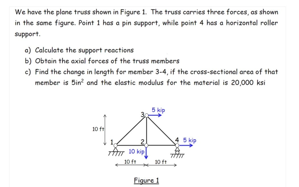
Transcribed Image Text:We have the plane truss shown in Figure 1. The truss carries three forces, as shown
in the same figure. Point 1 has a pin support, while point 4 has a horizontal roller
support.
a) Calculate the support reactions
b) Obtain the axial forces of the truss members
c) Find the change in length for member 3-4, if the cross-sectional area of that
member is 5in? and the elastic modulus for the material is 20,000 ksi
5 kip
10 ft
4 5 kip
TAm 10 kip
10 ft
10 ft
Figure 1
Expert Solution
This question has been solved!
Explore an expertly crafted, step-by-step solution for a thorough understanding of key concepts.

This is a popular solution!

Trending now
This is a popular solution!

Step by step
Solved in 4 steps with 1 images

Recommended textbooks for you
Mechanics of Materials (MindTap Course List)
Mechanical Engineering
ISBN:
9781337093347
Author:
Barry J. Goodno, James M. Gere
Publisher:
Cengage Learning
Mechanics of Materials (MindTap Course List)
Mechanical Engineering
ISBN:
9781337093347
Author:
Barry J. Goodno, James M. Gere
Publisher:
Cengage Learning