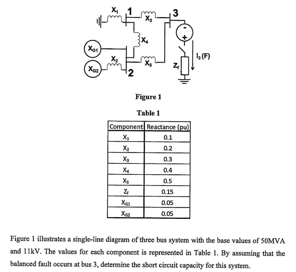
X4 3 X3 XG1 1 (F) X2 X5 Figure 1 Table 1 Component Reactance (pu) X1 0.1 X2 0.2 X3 0.3 X4 0.4 X5 0.5 ZE 0.15 XG1 0.05 XG2 0.05 Figure 1 illustrates a single-line diagram of three bus system with the base values of 50MVA and 11kV. The values for each component is represented in Table 1. By assuming that the balanced fault occurs at bus 3, determine the short circuit capacity for this system.
X4 3 X3 XG1 1 (F) X2 X5 Figure 1 Table 1 Component Reactance (pu) X1 0.1 X2 0.2 X3 0.3 X4 0.4 X5 0.5 ZE 0.15 XG1 0.05 XG2 0.05 Figure 1 illustrates a single-line diagram of three bus system with the base values of 50MVA and 11kV. The values for each component is represented in Table 1. By assuming that the balanced fault occurs at bus 3, determine the short circuit capacity for this system.

Power System Analysis and Design (MindTap Course List)
6th Edition
ISBN:9781305632134
Author:J. Duncan Glover, Thomas Overbye, Mulukutla S. Sarma
Publisher:J. Duncan Glover, Thomas Overbye, Mulukutla S. Sarma
Chapter5: Transmission Lines: Steady-state Operation
Section: Chapter Questions
Problem 5.58P

Related questions

Question
Transcribed Image Text:X4
3
X3
XG1
1 (F)
X2
X5
Figure 1
Table 1
Component Reactance (pu)
X1
0.1
X2
0.2
X3
0.3
X4
0.4
X5
0.5
0.15
XG1
0.05
XG2
0.05
Figure 1 illustrates a single-line diagram of three bus system with the base values of 50MVA
and 11kV. The values for each component is represented in Table 1. By assuming that the
balanced fault occurs at bus 3, determine the short circuit capacity for this system.
Expert Solution
This question has been solved!
Explore an expertly crafted, step-by-step solution for a thorough understanding of key concepts.

This is a popular solution!

Trending now
This is a popular solution!

Step by step
Solved in 4 steps with 3 images

Knowledge Booster


Learn more about
Need a deep-dive on the concept behind this application? Look no further. Learn more about this topic, electrical-engineering and related others by exploring similar questions and additional content below.Recommended textbooks for you
Power System Analysis and Design (MindTap Course …
Electrical Engineering
ISBN:
9781305632134
Author:
J. Duncan Glover, Thomas Overbye, Mulukutla S. Sarma
Publisher:
Cengage Learning
Power System Analysis and Design (MindTap Course …
Electrical Engineering
ISBN:
9781305632134
Author:
J. Duncan Glover, Thomas Overbye, Mulukutla S. Sarma
Publisher:
Cengage Learning