
Concept explainers
Videos
Figure P1.27 shows an ammeter (AM) and voltmeter (VM) connected to measure the current and voltage, respectively, for circuit element A.When current actually enters the + terminal of the ammeter, the reading is positive, and when current leaves the + terminal, the reading is negative. If the actual voltage polarity is positive at the + terminal of the VM, the reading is positive; otherwise, it is negative. (Actually, for the connection shown, the ammeter reads the sum of the current in element A and the very small current taken by the voltmeter. For purposes of this problem, assume that the current taken by the voltmeter is negligible.) Find the power for element A and state whether energy is being delivered to element A or taken from it if
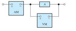
Figure P1.27
- the ammeter reading is +2 A and the voltmeter reading is +30 V;
Want to see the full answer?
Check out a sample textbook solution
Chapter 1 Solutions
Electrical Engineering: Principles & Applications Plus Mastering Engineering with Pearson eText -- Access Card Package (7th Edition)
Additional Engineering Textbook Solutions
Principles Of Electric Circuits
Programmable Logic Controllers
ELECTRICITY FOR TRADES (LOOSELEAF)
Principles and Applications of Electrical Engineering
Electric machinery fundamentals
Electric Motors and Control Systems


- Figure P1.27 shows an ammeter (AM) and voltmeter (VM) connected to measure thecurrent and voltage, respectively, for circuit element A. When current actually enters the + terminalof the ammeter, the reading is positive, and when current leaves the + terminalreading is negative. If the actual voltage polarity is positive at the + terminal of the VM, thereading is positive; otherwise, it is negative. (Actually, for the connection shown, the ammeterreads the sum of the current in element A and the very small current taken by the voltmeter. Forpurposes of this problem, assume that the current taken by the voltmeter is negligible.) Find thepower for element A and state whether energy is being delivered to element A or taken from it if a. the ammeter reading is +2 A and the voltmeter reading is +30 V.b. the ammeter reading is -2 A and the voltmeter reading is - 30 V.c. the ammeter reading is -2 A and the voltmeter reading is + 30 V.arrow_forwardA resistor of resistance ? is supplied by a battery which consists of voltage source ? in series with an internal resistance ?. Plot the power ? as a function of the resistance ? for 1 Ω < ? < 10 Ω given that ? = 12 V and ? = 4 Ω. From the resulting plot, when does the maximum power transfer occur and what is this maximum power being dissipated by the load?arrow_forwardThe circuit shown in Figure P1.67 is the electrical model for an electronic megaphone, in which the 8–Ω resistance models a loudspeaker, the source V x and the 5–kΩ resistance represent a microphone, and the remaining elements model an amplifier. Given that the power delivered to the 8–Ω resistance is 8 W, determine the current circulating in the right-hand loop of the circuit. Also, determine the value of the microphone voltage V x.arrow_forward
- Consider a gravity-driven LED bulb that provides 16 lumens of lighting. The device uses a 10-kg sandbag that is raised by human power to a 2-m height. For continuous lighting, the bag needs to be raised every 20 minutes. Using an efficacy of 150 lumens per watt for the LED bulb, determine (a) the velocity of the sandbag as it descends and (b) the overall efficiency of the device.arrow_forward. a) Calculate and plot the current flowing through the pn junctions of device #2 on your 3311 wafer as a function of voltage over the range of -3 volts to plus 1.5 (or so) volts on a linear scale. b) plot the I-V curve for the forward voltage on a log scale. c) What voltages correspond to 10 A/cm2, 100 A/cm2, 1000 A/cm2, 10,000 A/cm2 and 100,000 A/cm2? d) What is the current and current density when the applied voltage is equal to the built-in voltage? e) what are your thoughts on applying a voltage greater than the built-in voltage to a pn junction diode?arrow_forwardIf a cell has an E.M.F of E volts, an internal resistance of r ohms and supplies A current I ampere to a load, the terminal p.d. V volts is given by....arrow_forward
- Kindly put the given and solution. Given:VS1: -1 voltsVS2: 24 voltsB=beta: 150RE: 330 ohmsRC: 750 ohmsVC: ? voltsarrow_forwardA semiconductor substrate of 1 mm2 cross section is used to design a resistor. The doped-p concentration is 5'10^16 at/cm^3. and μp=500cm^2/Vxs We ask:(a) Calculate the electrical resistance for dimensions a= 100 mm, l= 500 mm, e= 0.1 mm.(b) The current density circulating for a voltage of 5 V.(c) The dopant concentration for R= 100 W.arrow_forwardIn a design task, a wire of 2000 m requires to exhibit a voltage drop of 2.5 Vwhen 3.2 A of current passes though it. Based on the Table Q1 (b) below, inyour opinion, which of the wire is the most suitable for aviation when the fuelsaving is another factor to be considered as well.arrow_forward
- A) What is an emf of self-induction? a) when there is an induced emf in a circuit due to a change of current in the circuit itself b) when there is an induced emf in a circuit due to a change of current in an adjacent circuit (one within magnetic reach) B) Under what conditions of current flow is a self-induced ernf produced? a) whenever the circuit is energized b) whenever the circuit is de-energized c) whenever the amount of current flow in the circuit varies d) all of the above C) What is the direction of a self-induced emf in relation to any change in current? a) the same direction as the current flow that caused it b) the opposite direction as the current flow that caused it c) may be either "a" or "b" d) neither "a" nor "b" D). In an inductive circuit, does the inductance have any effect on the flow of a steady current? a) yes b) noarrow_forwardInvestigate and explain the characteristics of ideal and real voltage and current sources.arrow_forwardDetermine the potential Uab and the current IE1 in the figurearrow_forward
 Power System Analysis and Design (MindTap Course ...Electrical EngineeringISBN:9781305632134Author:J. Duncan Glover, Thomas Overbye, Mulukutla S. SarmaPublisher:Cengage Learning