
Concept explainers
Videos
The circuit of Figure T1.3 has
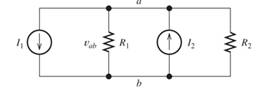
Figure T1.3
- Determine the value of
Want to see the full answer?
Check out a sample textbook solution
Chapter 1 Solutions
Modified Masteringengineering With Pearson Etext -- Standalone Access Card -- For Electrical Engineering: Principles & Applications
Additional Engineering Textbook Solutions
Electric machinery fundamentals
Introductory Circuit Analysis (13th Edition)
Electric Motors and Control Systems
Principles Of Electric Circuits
Fundamentals of Electric Circuits
Programmable Logic Controllers


- a) Calculate the currents I1, I2 and I3 indicated in the figure b) Explain Kirchhoff's law of meshes applied to solve the previous paragraph and how would you apply Kirchhoff's law of nodes? (no need to solve for Kirchhoff's law of nodes) c) What is the potential difference (observe the signs) between the points a & e (Vae)? d) Discuss the law of conservation of energy and verify it with your exercise data.arrow_forwardGiven:Vb = 100 voltsR = 10000 ohmsC = 200 μFAssuming that after a long period of time, the switch is flipped from position "A" to position "B" at t=0. Determine the current in the source-free circuit after 1 second.arrow_forward17. (I) Compute the voltage drop along a 21-m length of household no. 14 copper wire (used in 15-A circuits). The wire has diameter 1.628 mm and carries a 12-A current.arrow_forward
- Figure P1.27 shows an ammeter (AM) and voltmeter (VM) connected to measure thecurrent and voltage, respectively, for circuit element A. When current actually enters the + terminalof the ammeter, the reading is positive, and when current leaves the + terminalreading is negative. If the actual voltage polarity is positive at the + terminal of the VM, thereading is positive; otherwise, it is negative. (Actually, for the connection shown, the ammeterreads the sum of the current in element A and the very small current taken by the voltmeter. Forpurposes of this problem, assume that the current taken by the voltmeter is negligible.) Find thepower for element A and state whether energy is being delivered to element A or taken from it if a. the ammeter reading is +2 A and the voltmeter reading is +30 V.b. the ammeter reading is -2 A and the voltmeter reading is - 30 V.c. the ammeter reading is -2 A and the voltmeter reading is + 30 V.arrow_forwardTrue or False: 1. When there is electric current, there is electricity. 2. A wire resistance of 1 ohm per 1000 ft is bigger than a wire resistance of 1 ohm per 1000 m. 3. DC voltages are the usual voltages we generate in conventional power plants.arrow_forwardAssume that a 20 V voltage drop occurs across an element fromterminal 2 to terminal 1 and that a current of 4 A enters terminal 2.1. Specify the values of v and i for the polarity references shown inFig. 1.6(a)–(d).2. Calculate the power associated with the circuit element.3. Is the circuit element absorbing or delivering power?arrow_forward
- R1 = 1 kohms R2 = 1.4 kohms R3 = 6.8 kohms E = 8VD1: Si, rB = 2 ohms, rR = 215 kohms D2: Si, rB = 7 ohms, rR = 590 kohmsApplying first approximations, determine: a) Current through D1 b) Voltage across D_2 c) Voltage across R_3arrow_forwardDEGREE: ELECTRICAL ENGINEERING SUBJECT/COURSE: AC CIRCUITS NOTE: Please solve in this way. 1. Please have a good handwriting, some of the answers are not readable. Thank you! 2. GIVEN.(include symbols and units) 3. REQUIRED/FIND/MISSING (with symbol/s) 4. ILLUSTRATION (Required). 5. STEP-by-STEP SOLUTION with Formulas and Symbols. No Shortcut, No skipping, and detailed as possible 6. FINAL ANSWERS must be rounded up to three decimal places PROBLEM: • The magnitude of the complex power (apparentpower) supplied by a three-phase balanced wye-wye system is 3600VA. The line voltage is 208Vrms. If the line impedance is negligible and the power factor angle of the load is 25°, determine the load impedance.arrow_forwardPrepare & Analyze the whole Power System of the country "Philippines" Provide a Detailed Data like how Many Mega watts are generated etc etc that Cover All the things Must add a References. You can use the Internet openly. Thank youarrow_forward
- A copper conductor wire with a total length of 100ft is used in a 15 amp common household circuit has a resistance of 1.62 ohms/1000ft. If the circuit is fully loaded, determine the heat produced by the conductor? (Hint 1W = 3.413Btu/hr) a. 124.40 Btu/hr b. 99.83 Btu/hr c. 8.29 Btu/hr d. 177.50 Btu/hrarrow_forwardDEGREE: ELECTRICAL ENGINEERING SUBJECT/COURSE: AC CIRCUITS NOTE: Please solve in this way. 1. Please have a good handwriting, some of the answers are not readable. Thank you! 2. GIVEN.(include symbols and units) 3. REQUIRED/FIND/MISSING (with symbol/s) 4. ILLUSTRATION (Required). 5. STEP-by-STEP SOLUTION with Formulas and Symbols. No Shortcut, No skipping, and detailed as possible 6. FINAL ANSWERS must be rounded up to three decimal places PROBLEM: • A 300V(line) 3-phase supply feeds a star-connected load consisting of non-inductive resistors of 15, 6 and 10Ω connected to the R, Y and B lines, respectively. The phase sequence is RYB. Calculate the voltage across each resistor.arrow_forwardAfter a long time with the switch at position a, the switch moves to position b at time t=0. Assume that Vs = 22.7 V, R1 = 12 kΩ, R2 = 14 kΩ, R3 = 7 kΩ, and C = 194 nF. Calculate the voltage across the R2 resistor at time t=0.1ms. In this question, V = 22.7, R1 = 12kΩ, R2 = 14kΩ, R3 = 7kΩ and C = 194nF.arrow_forward
 Introductory Circuit Analysis (13th Edition)Electrical EngineeringISBN:9780133923605Author:Robert L. BoylestadPublisher:PEARSON
 Delmar's Standard Textbook Of ElectricityElectrical EngineeringISBN:9781337900348Author:Stephen L. HermanPublisher:Cengage Learning
 Programmable Logic ControllersElectrical EngineeringISBN:9780073373843Author:Frank D. PetruzellaPublisher:McGraw-Hill Education
 Fundamentals of Electric CircuitsElectrical EngineeringISBN:9780078028229Author:Charles K Alexander, Matthew SadikuPublisher:McGraw-Hill Education
 Electric Circuits. (11th Edition)Electrical EngineeringISBN:9780134746968Author:James W. Nilsson, Susan RiedelPublisher:PEARSON
 Engineering ElectromagneticsElectrical EngineeringISBN:9780078028151Author:Hayt, William H. (william Hart), Jr, BUCK, John A.Publisher:Mcgraw-hill Education,