
Loose Leaf for Engineering Circuit Analysis Format: Loose-leaf
9th Edition
ISBN: 9781259989452
Author: Hayt
Publisher: Mcgraw Hill Publishers
expand_more
expand_more
format_list_bulleted
Concept explainers
Videos
Textbook Question
Chapter 10.7, Problem 14P
If superposition is used on the circuit of Fig. 10.30, find V1 with (a) only the 20∠0° mA source operating; (b) only the 50∠−90° mA source operating.
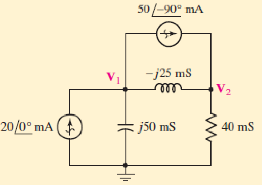
■ FIGURE 10.30
Expert Solution & Answer
Want to see the full answer?
Check out a sample textbook solution
Students have asked these similar questions
Employ phasor-based analysis to obtain an expression for i(t) in the circuit of Fig. 10.57.
Image attached.
For the system given below, Rf=10000 ohm, Ki=0.0125 Nm/A, J=10-6 kg.m2, n=800, Kb=0.0125V/(rad/second), Ra=6.25 ohm, Ks=0.1 A/ rad, with B=0 Nm/(rad/second); Determine the K value for the 9.9% overshoot.Calculate the time of overshoot that will occur for this situation.
Employ phasor analysis techniques to obtain expressions for the two mesh currents i1 and i2 as shown in Fig. 10.61.
Circuit attached in image.
Chapter 10 Solutions
Loose Leaf for Engineering Circuit Analysis Format: Loose-leaf
Ch. 10.1 - Find the angle by which i1 lags v1 if v1 = 120...Ch. 10.2 - Determine values for A, B, C, and if 40 cos(100t ...Ch. 10.2 - Let vs = 40 cos 8000t V in the circuit of Fig....Ch. 10.3 - Prob. 4PCh. 10.3 - If the use of the passive sign convention is...Ch. 10.4 - Let = 2000 rad/s and t = 1 ms. Find the...Ch. 10.4 - Transform each of the following functions of time...Ch. 10.4 - In the circuit of Fig. 10.17, both sources operate...Ch. 10.5 - With reference to the network shown in Fig. 10.19,...Ch. 10.5 - In the frequency-domain circuit of Fig. 10.21,...
Ch. 10.5 - Determine the admittance (in rectangular form) of...Ch. 10.6 - Use nodal analysis on the circuit of Fig. 10.23 to...Ch. 10.6 - Use mesh analysis on the circuit of Fig. 10.25 to...Ch. 10.7 - If superposition is used on the circuit of Fig....Ch. 10.7 - Prob. 15PCh. 10.7 - Determine the current i through the 4 resistor of...Ch. 10.8 - Select some convenient reference value for IC in...Ch. 10 - Evaluate the following: (a) 5 sin (5t 9) at t =...Ch. 10 - (a) Express each of the following as a single...Ch. 10 - Prob. 3ECh. 10 - Prob. 4ECh. 10 - Prob. 5ECh. 10 - Calculate the first three instants in time (t 0)...Ch. 10 - (a) Determine the first two instants in time (t ...Ch. 10 - The concept of Fourier series is a powerful means...Ch. 10 - Household electrical voltages are typically quoted...Ch. 10 - Prob. 10ECh. 10 - Assuming there are no longer any transients...Ch. 10 - Calculate the power dissipated in the 2 resistor...Ch. 10 - Prob. 13ECh. 10 - Prob. 14ECh. 10 - Prob. 15ECh. 10 - Express the following complex numbers in...Ch. 10 - Prob. 17ECh. 10 - Prob. 18ECh. 10 - Evaluate the following, and express your answer in...Ch. 10 - Perform the indicated operations, and express the...Ch. 10 - Insert an appropriate complex source into the...Ch. 10 - For the circuit of Fig. 10.51, if is = 2 cos 5t A,...Ch. 10 - In the circuit depicted in Fig. 10.51, if is is...Ch. 10 - Employ a suitable complex source to determine the...Ch. 10 - Transform each of the following into phasor form:...Ch. 10 - Prob. 26ECh. 10 - Prob. 27ECh. 10 - The following complex voltages are written in a...Ch. 10 - Assuming an operating frequency of 50 Hz, compute...Ch. 10 - Prob. 30ECh. 10 - Prob. 31ECh. 10 - Prob. 32ECh. 10 - Assuming the passive sign convention and an...Ch. 10 - The circuit of Fig. 10.53 is shown represented in...Ch. 10 - (a) Obtain an expression for the equivalent...Ch. 10 - Determine the equivalent impedance of the...Ch. 10 - (a) Obtain an expression for the equivalent...Ch. 10 - Determine the equivalent admittance of the...Ch. 10 - Prob. 40ECh. 10 - Prob. 41ECh. 10 - Find V in Fig. 10.55 if the box contains (a) 3 in...Ch. 10 - Prob. 43ECh. 10 - Prob. 44ECh. 10 - Design a suitable combination of resistors,...Ch. 10 - Design a suitable combination of resistors,...Ch. 10 - For the circuit depicted in Fig. 10.58, (a) redraw...Ch. 10 - For the circuit illustrated in Fig. 10.59, (a)...Ch. 10 - Referring to the circuit of Fig. 10.59, employ...Ch. 10 - In the phasor-domain circuit represented by Fig....Ch. 10 - With regard to the two-mesh phasor-domain circuit...Ch. 10 - Employ phasor analysis techniques to obtain...Ch. 10 - Determine IB in the circuit of Fig. 10.62 if and ....Ch. 10 - Determine V2 in the circuit of Fig. 10.62 if and ....Ch. 10 - Employ phasor analysis to obtain an expression for...Ch. 10 - Determine the current ix in the circuit of Fig....Ch. 10 - Obtain an expression for each of the four...Ch. 10 - Determine the nodal voltages for the circuit of...Ch. 10 - Prob. 59ECh. 10 - Obtain an expression for each of the four mesh...Ch. 10 - Determine the individual contribution each current...Ch. 10 - Determine V1 and V2 in Fig. 10.68 if I1 = 333 mA...Ch. 10 - Prob. 63ECh. 10 - Obtain the Thvenin equivalent seen by the (2 j) ...Ch. 10 - The (2 j) impedance in the circuit of Fig. 10.69...Ch. 10 - With regard to the circuit depicted in Fig. 10.70,...Ch. 10 - Prob. 67ECh. 10 - Determine the individual contribution of each...Ch. 10 - Determine the power dissipated by the 1 resistor...Ch. 10 - The source Is in the circuit of Fig. 10.75 is...Ch. 10 - Prob. 72ECh. 10 - (a) Calculate values for IL, IR, IC, VL, VR, and...Ch. 10 - In the circuit of Fig. 10.77, (a) find values for...Ch. 10 - The voltage source Vs in Fig. 10.78 is chosen such...Ch. 10 - For the circuit shown in Fig. 10.79, (a) draw the...Ch. 10 - For the circuit shown in Fig. 10.80, (a) draw the...Ch. 10 - (a) Replace the inductor in the circuit of Fig....Ch. 10 - Design a purely passive network (containing only...
Knowledge Booster


Learn more about
Need a deep-dive on the concept behind this application? Look no further. Learn more about this topic, electrical-engineering and related others by exploring similar questions and additional content below.Similar questions
- Referring to the circuit of Fig. 10.59, employ phasor-based analysis techniques to determine the two nodal voltages. (Circuit attached in image).arrow_forwardA parabolic reflector antenna with a diameter of 22 meters operates at frequency of 5GHz. calculate the power gain, G (dB) of the antenna if the aperture efficiency is 50%.arrow_forwardDetermine the Norton equivalent of the circuit in Fig. 10.30 as seen from terminals a-b. Use the equivalent to find Io.arrow_forward
- Explore the challenges and benefits of implementing power electronics-based grid solutions like STATCOM (Static Synchronous Compensator) for voltage control and stability.arrow_forwardA 25V, 2.5kHz supply is connected to a network comprising a variable capacitor in parallel with a coil of resistance 250 ohms and inductance 80 mH. Determine, for the condition when the supply current is a minimum the capacitance of the capacitor the dynamic impedance the supply current the upper half-power frequency the value of the circuit impedance at the -3dB frequenciesarrow_forwardA PV system delivers power to a DC motor that in turn feeds a water pump. The DC motor is rated for 1.0 kW and is 85% efficient. Each PV module has 36 solar cells, arranged in a 9 x 4 matrix. The cell size is 125 mm x 125 mm and cell efficiency is 12%. Calculate the number of modules required in the array. Assume global radiation incidence normal to the panel to be 1.0 kW/m2.arrow_forward
- Please sholve for the i hat, j hat, at k hat. Sample solutions also indicated below.arrow_forwardWhich row represent the most stable system and why? nyquist and root locus plot attached.arrow_forwardThe numerical input/output mean optical power ratio in a 1 km, length of optical fiber is found to be 2.5. Calculate the received mean optical power when a mean optical power of 1 mW is launched into a 5 km length of the fiber (assurning no joints or connectors).arrow_forward
- 23. Calculate the reactance of a peterson coil suitable for 1 33kV, 3phase transmission system of which the capacitance to eart of each conductor is 3.2μFarrow_forwardA system has the following characteristic equation: s^4+ s^3+ 3s^2+ 2s + 2 = 0 Using the Routh-Hurwitz method, checka. How many roots are to the right of the imaginary axis?b. Is the system stable?.arrow_forwardA 230 kV, 3-phase, 50 Hz, 200 km transmission line has a capacitance to earth of 0.03 µF/km per phase. Calculate the inductance and kVA rating of the Peterson coil used for earthing the above system.arrow_forward
arrow_back_ios
SEE MORE QUESTIONS
arrow_forward_ios
Recommended textbooks for you
 Introductory Circuit Analysis (13th Edition)Electrical EngineeringISBN:9780133923605Author:Robert L. BoylestadPublisher:PEARSON
 Delmar's Standard Textbook Of ElectricityElectrical EngineeringISBN:9781337900348Author:Stephen L. HermanPublisher:Cengage Learning
 Programmable Logic ControllersElectrical EngineeringISBN:9780073373843Author:Frank D. PetruzellaPublisher:McGraw-Hill Education
 Fundamentals of Electric CircuitsElectrical EngineeringISBN:9780078028229Author:Charles K Alexander, Matthew SadikuPublisher:McGraw-Hill Education
 Electric Circuits. (11th Edition)Electrical EngineeringISBN:9780134746968Author:James W. Nilsson, Susan RiedelPublisher:PEARSON
 Engineering ElectromagneticsElectrical EngineeringISBN:9780078028151Author:Hayt, William H. (william Hart), Jr, BUCK, John A.Publisher:Mcgraw-hill Education,
Introductory Circuit Analysis (13th Edition)
Electrical Engineering
ISBN:9780133923605
Author:Robert L. Boylestad
Publisher:PEARSON
Delmar's Standard Textbook Of Electricity
Electrical Engineering
ISBN:9781337900348
Author:Stephen L. Herman
Publisher:Cengage Learning
Programmable Logic Controllers
Electrical Engineering
ISBN:9780073373843
Author:Frank D. Petruzella
Publisher:McGraw-Hill Education
Fundamentals of Electric Circuits
Electrical Engineering
ISBN:9780078028229
Author:Charles K Alexander, Matthew Sadiku
Publisher:McGraw-Hill Education
Electric Circuits. (11th Edition)
Electrical Engineering
ISBN:9780134746968
Author:James W. Nilsson, Susan Riedel
Publisher:PEARSON
Engineering Electromagnetics
Electrical Engineering
ISBN:9780078028151
Author:Hayt, William H. (william Hart), Jr, BUCK, John A.
Publisher:Mcgraw-hill Education,
Nodal Analysis for Circuits Explained; Author: Engineer4Free;https://www.youtube.com/watch?v=f-sbANgw4fo;License: Standard Youtube License