
Concept explainers
Find the reaction and plot the shear and bending moment diagram.
Answer to Problem 15P
The end moments at the member A
Explanation of Solution
Fixed end moment:
Formula to calculate the fixed moment for point load with equal length are
Formula to calculate the fixed moment for point load with unequal length are
Formula to calculate the fixed moment for UDL is
Formula to calculate the fixed moment for deflection is
Calculation:
Consider the flexural rigidity EI of the beam is constant.
Show the free body diagram of the entire beam as in Figure 1.
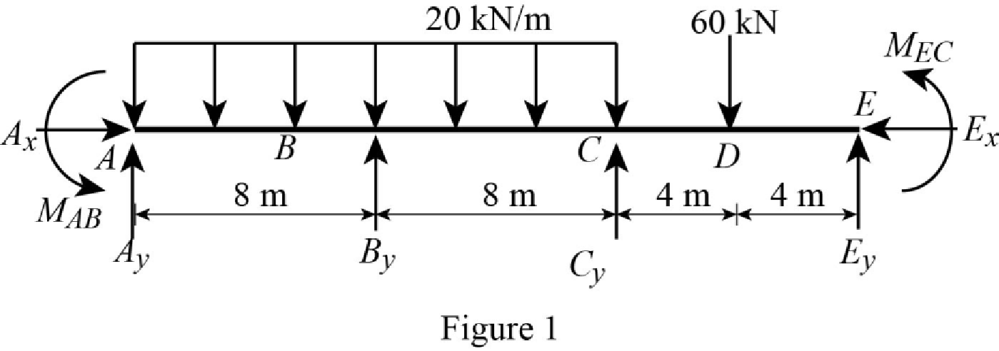
Refer Figure 1,
Calculate the fixed end moment for AB.
Calculate the fixed end moment for BA.
Calculate the fixed end moment for BC.
Calculate the fixed end moment for CB.
Calculate the fixed end moment for CE.
Calculate the fixed end moment for EC.
Chord rotations:
Show the free body diagram of the chord rotation of the beam as in Figure 2.
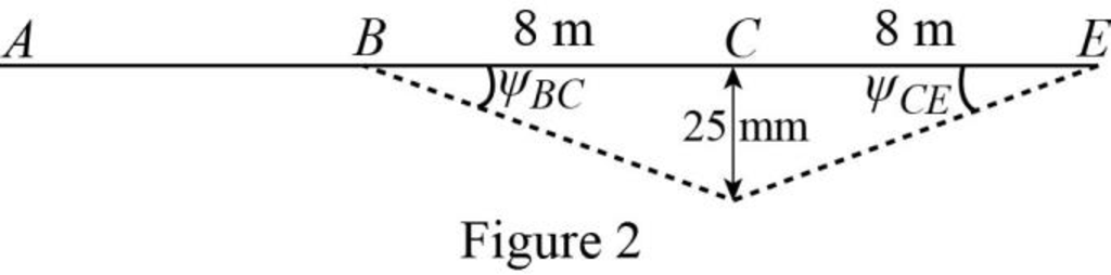
Calculate the chord rotation of the beam BC.
Calculate the chord rotation of the beam CE.
Calculate the slope deflection equation for the member AB.
Here,
Substitute
Calculate the slope deflection equation for the member BA.
Substitute
Calculate the slope deflection equation for the member BC.
Substitute
Calculate the slope deflection equation for the member CB.
Substitute
Calculate the slope deflection equation for the member CE.
Substitute
Calculate the slope deflection equation for the member EC.
Substitute
Write the equilibrium equation as below.
Substitute equation (2) and equation (3) in above equation.
Write the equilibrium equation as below.
Substitute equation (4) and equation (5) in above equation.
Solve the equation (7) and equation (8).
Calculate the moment about AB.
Substitute
Calculate the moment about BA.
Substitute
Calculate the moment about BC.
Substitute
Calculate the moment about CB.
Substitute
Calculate the moment about CE.
Substitute
Calculate the moment about EC.
Substitute
Consider the member AB of the beam:
Show the section free body diagram of the member AB, BC and CE as in Figure 3.
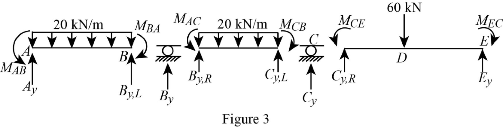
Calculate the vertical reaction at the left end of the joint B by taking moment about point A.
Calculate the horizontal reaction at point A by resolving the horizontal equilibrium.
Calculate the vertical reaction at point A by resolving the vertical equilibrium.
Consider the member BC of the beam:
Calculate the vertical reaction at the right end of the joint B by taking moment about point C.
Calculate the vertical reaction at the left end of joint C by resolving the vertical equilibrium.
Calculate the total reaction at point B.
Substitute
Calculate the vertical reaction at the right end of the joint C by taking moment about point E.
Calculate the horizontal reaction at point E by resolving the horizontal equilibrium.
Calculate the vertical reaction at point E by resolving the vertical equilibrium.
Calculate the total reaction at point C.
Substitute
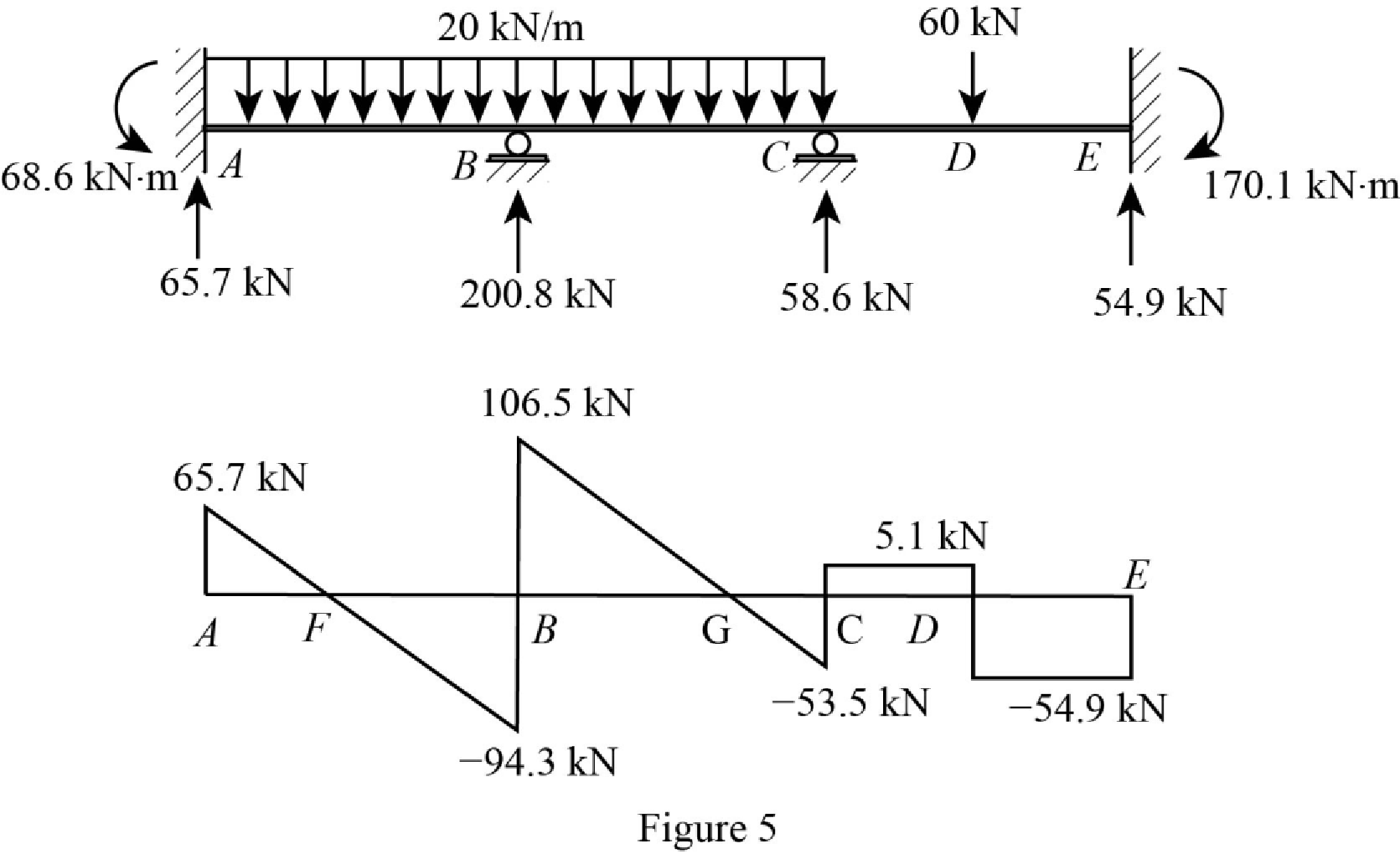
Show the reactions of the beam in Figure 4.
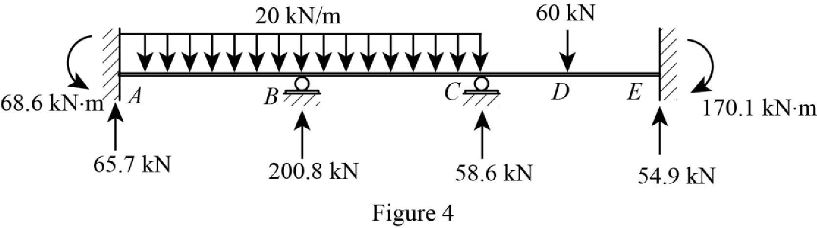
Refer Figure 4,
Shear diagram:
Point A:
Point B:
Point C:
Point E:
Plot the shear force diagram of the beam as in Figure 5.
Show the shear diagram of the section AB as in Figure 6.
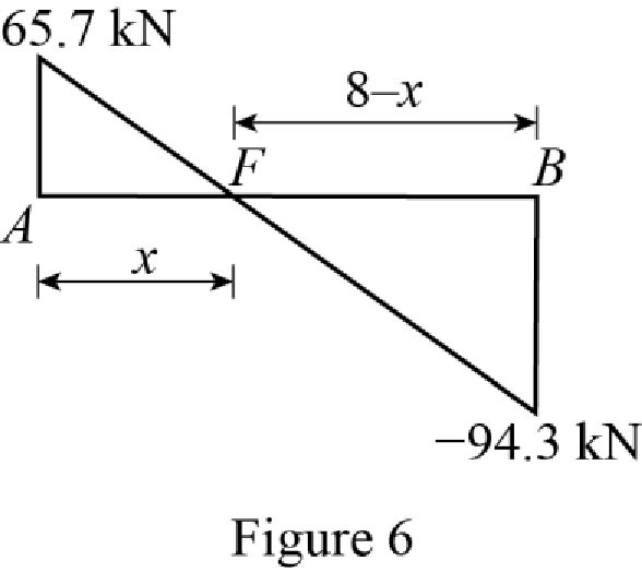
Use the similar triangle concept, to find the location of the maximum bending moment.
Show the shear diagram of the section BC as in Figure 7.
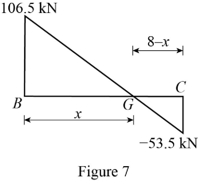
Use the similar triangle concept, to find the location of the maximum bending moment.
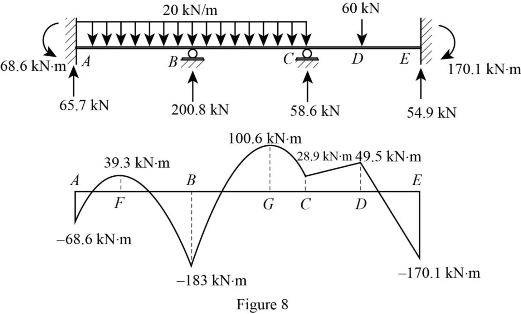
Refer Figure 4,
Bending moment diagram:
Point A:
Point F:
Point B:
Point G:
Point C:
Point D:
Point E:
Plot the bending moment diagram of the beam as in Figure 8.
Want to see more full solutions like this?
Chapter 15 Solutions
Structural Analysis

