
Concept explainers
Videos
A comparator will have a positive output whenever the noninverting input is greater than the inverting input.
Whether the given statement is true or false.
Answer to Problem 1TFQ
The statement is true.
Explanation of Solution
Given:
When the value of the non-inverting terminal is greater than the inverting terminal than the comparator will have a positive output.
The circuit diagram of the op-amp is:
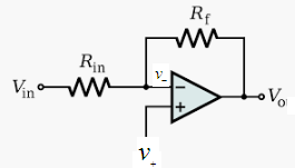
The output is given as:
Now, when the value of the non-inverting input is greater than the inverting input than the output of the comparator op-amp is positive.
Similarly, when the non-inverting terminal is less than the inverting terminal then the output will be negative:
Therefore, the given statement is true that the comparator output will be positive if the value of the non-inverting terminal is greater than the inverting terminal.
Want to see more full solutions like this?
Chapter 19 Solutions
Electronics Fundamentals: Circuits, Devices & Applications


- The output voltage of an opamp is v(t)=10sin(200t) V. Find out the value of the slew rate of the opamp.arrow_forwardDraw the schematic diagram of the series-positive limiter and the series-negative limiter; additionally, draw the output curves for each circuit.arrow_forwardWhat is the value of iC (0+) for the following circuit?arrow_forward
- I_rev is the reverse bias current, also labe the appropriate spot on the IV plot with the parameter name I_rev. Please show all work and thank youarrow_forward5: Draw the circuit diagram of a non-inverting comparator and inverting comparatorarrow_forwardThe output current is iR(t). Make a state space representation of the circuit below.arrow_forward
- Draw the v0 output signal according to the given input signal (R=160Ω)arrow_forwardA .............. Answer transducer is used to measure the pressure of gases or liquids.arrow_forwardIt refers to the application of external voltage across the two terminals of the device to extract a response biasing loading sourcing dopingarrow_forward
 Introductory Circuit Analysis (13th Edition)Electrical EngineeringISBN:9780133923605Author:Robert L. BoylestadPublisher:PEARSON
 Delmar's Standard Textbook Of ElectricityElectrical EngineeringISBN:9781337900348Author:Stephen L. HermanPublisher:Cengage Learning
 Programmable Logic ControllersElectrical EngineeringISBN:9780073373843Author:Frank D. PetruzellaPublisher:McGraw-Hill Education
 Fundamentals of Electric CircuitsElectrical EngineeringISBN:9780078028229Author:Charles K Alexander, Matthew SadikuPublisher:McGraw-Hill Education
 Electric Circuits. (11th Edition)Electrical EngineeringISBN:9780134746968Author:James W. Nilsson, Susan RiedelPublisher:PEARSON
 Engineering ElectromagneticsElectrical EngineeringISBN:9780078028151Author:Hayt, William H. (william Hart), Jr, BUCK, John A.Publisher:Mcgraw-hill Education,