
Concept explainers
Videos
The drawing shown is of a mounting fixture to locate and orient a rod (not shown) through the large bore. The fixture will be bolted to a frame through the four bolt holes that are countersunk to recess the bolt heads. The bolt holes have too much clearance to properly align the rod, so the fixture will be aligned with two locating pins in the frame that will fit in the Ø6 hole and slot.
(a) Determine the minimum diameter allowed for the countersink.
(b) Determine the maximum depth allowed for the countersink.
(c) Determine the diameter of the bolt holes at MMC.
(d) Identify every feature that qualifies as a feature of size.
(e) The width of the base is specified with a basic dimension of 60, with no tolerance. (Note that as a feature of size, it could have had a tolerance directly specified.) What are the minimum and maximum allowed dimensions for the base width? Explain how they are determined.
Problem 20–27
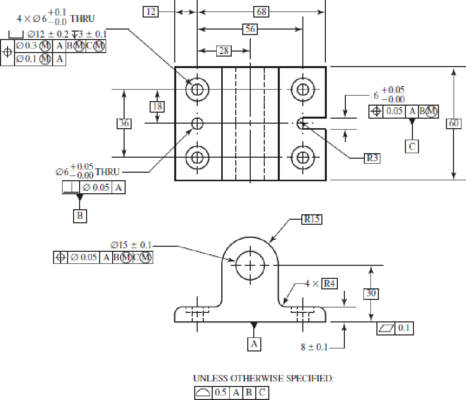
(f) Describe the datum features A, B, and C. Describe their corresponding datums. Describe the datum reference frame that is defined by applying A, B, and C in that order. Describe how the part is stabilized by these datums. Explain why this is more appropriate for this application than using the edges of the base for datums B and C. (Notice that the basic dimensions are either measured from, or implied to be centered on, the datums of the datum reference frame.)
(g) If datum feature B is produced with a diameter of Ø6.00, what is the diameter of the tolerance zone in which its axis must lie? What if it is produced at Ø6.05?
(h) If the bolt holes are produced at Ø6.0, what is the diameter of the tolerance zones locating the bolt hole pattern with respect to the true position specified by the basic dimensions? What if the bolt holes are produced at Ø6.1?
(i) If the bolt holes are produced at Ø6.0, what is the diameter of the tolerance zones locating the position of the bolt holes with respect to one another? What if the bolt holes are produced at Ø6.1?
(j) Explain why the Ⓜ modifier is appropriate for the bolt hole position tolerance.
(k) For the large bore, explain what provides control of each of the following: orientation, straightness of its center axis, and cylindricity of its surface.
(l) Assume the part is cast, and the casting operation can provide a surface profile tolerance of less than 0.5. Which surfaces can likely be left in the as-cast condition without compromising any of the requirements of the drawing? How would this change if the drawing were modified to use the edges of the base as datum features B and C, while still maintaining the functional goals for the alignment of the rod?
(a)
The minimum diameter allowed for the countersink.
Answer to Problem 27P
The minimum diameter allowed for the countersink is
Explanation of Solution
Write the expression for the minimum diameter allowed for the countersink.
Here, the nominal diameter is
Conclusion:
The countersink diameter is specified as
Substitute
Thus, the minimum diameter allowed for the countersink is
(b)
The maximum countersink depth.
Answer to Problem 27P
The maximum countersink depth is
Explanation of Solution
Write the expression for the maximum countersink depth.
Here, the nominal tolerance for counter sink depth is
Conclusion:
The countersink depth is specified as
Substitute
Thus, the maximum countersink depth is
(c)
The diameter of the bolt holes at MMC.
Answer to Problem 27P
The diameter of the bolt holes at MMC is
Explanation of Solution
Write the expression for the diameter of the bolt holes at MMC.
Here, the nominal diameter of the hole is
Conclusion:
The bolt holes at MMC is specified as
Substitute
Thus, the diameter of the bolt holes at MMC is
(d)
The feature that qualifies as a feature of size.
Answer to Problem 27P
The feature that qualifies as a feature of size are:
- The maximum diameter of the bolt is
- The minimum diameter of the bolt is
- The maximum thickness of the clamping part is
- The minimum thickness of the clamping part is
Explanation of Solution
The term “feature of size” refers to a feature that has a size that can be measured across two opposing points, such as a hole, diameter, or slot.
The features of size are hole diameters and counter bore diameter, the slot width, the base widths, the base thickness, and the centre protrusion width.
Conclusion:
Refer to Figure 20-27 to obtain the feature of size as:
- The maximum diameter of the bolt is
- The minimum diameter of the bolt is
- The maximum thickness of the clamping part is
- The minimum thickness of the clamping part is
(e)
The minimum allowed dimension for the base width.
The maximum allowed dimension for the base width.
Answer to Problem 27P
The minimum allowed dimension for the base width is
The maximum allowed dimension for the base width is
Explanation of Solution
Write the expression for the minimum allowed dimension for the base width.
Here, the base width is
Write the expression for the maximum allowed dimension for the base width.
Here, the upper tolerance is
Conclusion:
The default surface profile tolerance in the note provide a tolerance zone around all the surfaces of
Substitute
Thus, the minimum allowed dimension for the base width is
Substitute
Thus, the maximum allowed dimension for the base width is
(f)
The description for the datum feature A.
The description for the datum feature B.
The description for the datum feature C.
The description for the datum reference frame.
The description for the part which is stabilized by this datum’s.
Whether it is appropriate to locate a part with respect to locating pins or with respect to the edge of a part.
Explanation of Solution
- Datum feature A: - It is the bottom surface of the feature. Its datum is a theoretical plane corresponding to a datum feature simulator, such as machine table.
- Datum feature B: - It is the surface of the hole. Its datum is the centre axis corresponding to a datum feature simulator, such that the largest gauge pin just touching the high point of the hole while being held perpendicular to datum A.
- Datum feature C: - It is the surface of the slot. Its datum is the centre plane corresponding to a datum feature simulator, such that the largest gauge block just touching the high points of the slot while being held perpendicular to datum A.
The datum reference frame:-It is an important part of an object, such as hole, set of holes, pairs of surface and lines. It is used as a reference to define the geometry of the object. Here, the datum reference frame is made of the three mutually perpendicular planes, with the origin of the coordinate axes at the bottom centre of the datum B hole.
The description for the part, which stabilized by the datum’s for manufacturing or inspections are:
- 1. Constrain the base to be in contact with a datum feature simulator corresponding to datum A.
- 2. Constrain the translation of the part on datum A with a gauge pin in the datum feature B hole.
- 3. Constrain the final rotation of the part with a gauge pin or block in the groove.
Fixture: The purpose of the fixture is to locate and orient the large bores. The bores are located with respect to the following datum’s.
- 1. The bottom surface (datum A).
- 2. The pin hole (datum B).
- 3. The groove (datum C).
The edge of the base is not touching anything for the alignment, and can consequently have much looser tolerances. Hence, it is usually easier and cheaper to precisely locate a part with respect to locating pins than with respect to the edge of the part.
Thus, it is more appropriate to locate a part with respect to locating pins than with respect to the edge of the part.
(g)
The diameter of the tolerance zone at produced diameter of
The diameter of the tolerance zone at produced diameter of
Answer to Problem 27P
The diameter of the tolerance zone at produced diameter of
The diameter of the tolerance zone at produced diameter of
Explanation of Solution
For the given feature, the tolerance zone is regardless of the feature size as there is no any material modifier that can specify the tolerance zone associated with the hole. Hence, the diameter of the tolerance zone is specified as
Conclusion:
Thus, the diameter of the tolerance zone at produced diameter of
Thus, the diameter of the tolerance zone at produced diameter of
(h)
The diameter of the tolerance zones at produced diameter of
The diameter of the tolerance zones at produced diameter of
Answer to Problem 27P
The diameter of the tolerance zones at produced diameter of
The diameter of the tolerance zones at produced diameter of
Explanation of Solution
When manufactured at MMC.
The top line of the position control of the bolt holes specifies the diameter of the tolerance zones at produced diameter of
When manufactured at LMC.
The diameter of the tolerance zone is
Thus, the diameter of the tolerance zones at produced diameter of
Conclusion:
Thus, the diameter of the tolerance zones at produced diameter of
Thus, the diameter of the tolerance zones at produced diameter of
(i)
The diameter of the tolerance zones locating the position of the bolts holes with respect to one another at produced diameter of
The diameter of the tolerance zones locating the position of the bolts holes with respect to one another at produced diameter of
Answer to Problem 27P
The diameter of the tolerance zones locating the position of the bolts holes with respect to one another at produced diameter of
The diameter of the tolerance zones locating the position of the bolts holes with respect to one another at produced diameter of
Explanation of Solution
The second line of the position control of the bolt holes specifies the tolerance of
For the bolt holes when manufactured at the MMC, the diameter of the tolerance zones locating the position of the bolts holes with respect to one another at produced diameter of
For the bolt holes when manufactured at the LMC, the diameter of the tolerance zone is
Conclusion:
Thus, the diameter of the tolerance zones locating the position of the bolts holes with respect to one another at produced diameter of
Thus, the diameter of the tolerance zones locating the position of the bolts holes with respect to one another at produced diameter of
(j)
The reason of being that the (M) modifier is appropriate for the bolt hole position tolerance.
Explanation of Solution
The (M) modifier is appropriate for the bolt hole position tolerance as the MMC ensures a minimum clearance for the bolts in their holes. Though they allows greater deviations from ideal if the produced holes are larger.
(k)
The parameter to control the orientation and straightness of its centre axis.
The parameter to control the cylindricity of its surface.
Explanation of Solution
The orientation and the straightness of the axis are controlled by the position tolerance zone which is specified in the feature control frame directly under the diameter dimension for the bore.
The position tolerance specifies a cylindrical tolerance zone that the axis of the hole must be within, thus controlling its orientation and straightness.
Cylindricity is a control of the surface of the bore. It could be controlled either by the default profile of the surface control, specified with the note at the bottom of the drawing, or by Rule # 1.
Here, the Rule #1 has the tighter tolerance, so it controls the cylindricity of the bore.
(l)
The surfaces that are controlled by the default surface profile tolerance.
The changes in the drawing with the use of the edges of the base as datum feature.
Explanation of Solution
All the exterior surfaces are controlled by the default surface profile tolerance, but the bottom surface is not controlled by the default surface profile tolerance.
Hence, the as-cast is sufficient for controlling the surfaces.
The drawing is modified because the edges of the base were used as datum features. This modification also effects the controlling of the surfaces. These surfaces would need to be controlled more tightly in order to locate the critical holes from them. Also, the edges of the base could not be left as-cast.
Want to see more full solutions like this?
Chapter 20 Solutions
Shigley's Mechanical Engineering Design (McGraw-Hill Series in Mechanical Engineering)


- Two shafts A and B are connected by rolling cones and turn in the opposite direction. Shaft A makes 300 rpm while shaft B makes 80 rpm. Calculate the cone angle of each cone and the diameter of each base if the base of cone B is 3 in. from the vertex. 8 = 30° CONE ANGLE OF A: CONE ANGLE OF B: DIAMETER OF A: DIAMETER OF B:arrow_forwarda)draw the top view of the obeject b)from the top view draw a downward projection line for each project c)draw a A-A section by referring to the arrow correction : diameter for the centre circle is 12mm and 24 mmarrow_forwardA winch drum has an effective diameter 0.25m and is turning at 22 rpm. What is the resulting line speed in m/min? Give your answer to 1 decimal place without units eg if you think it is 102.341m/min, simply type 102.3.arrow_forward
- Please show complete solution of part 6arrow_forwardOn drawing 31A059, what is dimension F? Allarrow_forwardOn section view AAa) What type of bearing is it?b) Is the assembly of these bearings rotating shaft or rotating hub?c) Is the mounting of the bearings in X, in O, …?d) Which rings (inner or outer) are mounted with interference?e) How many stops on the shaft are blocked?f) How many stops in the bore are blocked?g) Give the average tolerance of the seats of the inner rings located on the shaft.h) Give the average tolerance of the seats of the outer rings located on the bore.arrow_forward
- Solve for Problem 2, when RN1 = 0145arrow_forwardA cone, base diameter 65 mm and axis 75 mm, is lying on the ground on one of itsgenerators with the axis parallel to the VP. A section plane which is parallel to the VP, cutsthe cone 6 mm away from the axis. Draw the sectional front view.arrow_forwardOn the cylinder, specify straightness of a median line of .010 at MMCarrow_forward
 International Edition---engineering Mechanics: St...Mechanical EngineeringISBN:9781305501607Author:Andrew Pytel And Jaan KiusalaasPublisher:CENGAGE L