
Concept explainers
Videos
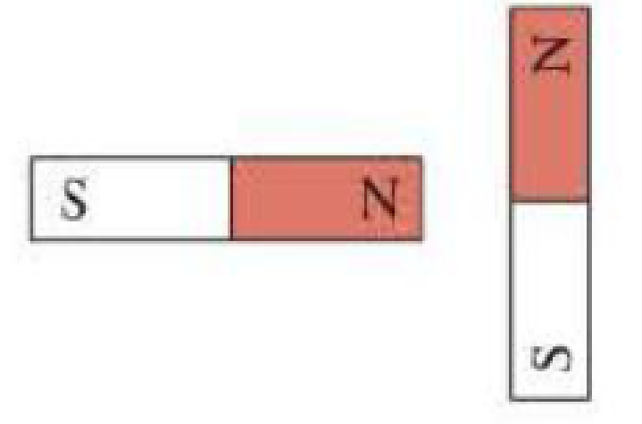
In Figure Q24.1, suppose the magnet on the right is fixed in place and the magnet on the left is free to pivot about its center. Will the magnet on the left start to rotate? If so, will it initially rotate clockwise or counterclockwise?
Figure Q24.1
To check: the left side magnet’s rotation and find the initial rotating direction of this magnet.
Answer to Problem 1CQ
The left side magnet starts rotating and it is rotating in the direction of clockwise.
Explanation of Solution
Given data:
Refer Figure Q24.1 in the textbook for two magnet arrangement.
Consider that the north pole of the magnet is expressed as “N” and the south pole of the magnet is expressed as “S”.
Explanation:
Consider the same poles of magnets repel each other and opposite poles of magnets attract each other.
The magnet, which is placed in the left side, will rotate in direction of clockwise because two N poles of the two magnets repel each other and the N pole of left magnet gets attracted by the S pole of right magnet. Then, the left magnet’s S pole is attracted to the N pole of the fixed magnet.
Therefore, the left magnet gets rotating due to opposite poles attraction and same poles repel.
Conclusion:
Thus, the left side magnet starts rotating and it is rotating in the direction of clockwise.
Want to see more full solutions like this?
Chapter 24 Solutions
COLLEGE PHYSICS,TECH.UPDTE-W/MOD.MASTRG
Additional Science Textbook Solutions
Conceptual Physical Science (6th Edition)
Physics for Scientists and Engineers: A Strategic Approach, Vol. 1 (Chs 1-21) (4th Edition)
University Physics Volume 2
Cosmic Perspective Fundamentals
Applied Physics (11th Edition)


- (a) Find the direction of the force on a proton (a positively charged particle) moving through the magnetic fields in Figure P19.2, as shown. (b) Repeat part (a), assuming the moving particle is an electron. Figure P19.2 Problems 2 and 22.arrow_forwardDetermine the initial direction of the deflection of charged particles as they enter the magnetic fields as shown in Figure P22.2. Figure P22.2.arrow_forwardA proton moving in the plane of the page has a kinetic energy of 6.00 MeV. A magnetic field of magnitude H = 1.00 T is directed into the page. The proton enters the magnetic field with its velocity vector at an angle = 45.0 to the linear boundary of' the field as shown in Figure P29.80. (a) Find x, the distance from the point of entry to where the proton will leave the field. (b) Determine . the angle between the boundary and the protons velocity vector as it leaves the field.arrow_forward
- One long wire carries current 30.0 A to the left along the x axis. A second long wire carries current 50.0 A to the right along the line (y = 0.280 m, z = 0). (a) Where in the plane of the two wires is the total magnetic field equal to zero? (b) A particle with a charge of 2.00 C is moving with a velocity of 150iMm/s along the line (y = 0.100 m, z = 0). Calculate the vector magnetic force acting on the particle. (c) What If? A uniform electric field is applied to allow this particle to pass through this region undetected. Calculate the required vector electric field.arrow_forwardTwo long, straight, parallel wires carry currents that are directed perpendicular to the page as shown in Figure P30.9. Wire 1 carries a current I1, into the page (in the negative z direction) and passes through the x axis at x = +. Wire 2 passes through the x axis at x = 2a and carries an unknown current I2. The total magnetic field at the origin due to the current-carrying wires has the magnitude 20I1(2a). The current I2 can have either of two possible values, (a) Find the value of with the smaller magnitude, stating it in terms of I1, and giving its direction. (b) Find the other possible value of I2.arrow_forwardA horizontal power line of length 58 m carries a current of 2.2 kA as shown in Figure P19.34. Earths magnetic field at this location has a magnitude equal to 5.0 105. T and makes an angle of 65 with the power line. Find the magnitude and direction of the magnetic force on the power line. Figure P19.34arrow_forward
- In Figure P22.43, the current in the long, straight wire is I1 = 5.00 A and the wire lies in the plane of the rectangular loop, which carries a current I2 = 10.0 A. The dimensions in the figure are c = 0.100 m, a = 0.150 m, and = 0.450 m. Find the magnitude and direction of the net force exerted on the loop by the magnetic field created by the wire. Figure P22.43 Problems 43 and 44.arrow_forwardAn infinitely long wire carrying a current I is bent at a right angle as shown in Figure P22.30. Determine the magnetic field at point P, located a distance x from the corner of the wire. Figure P22.30arrow_forward
 Principles of Physics: A Calculus-Based TextPhysicsISBN:9781133104261Author:Raymond A. Serway, John W. JewettPublisher:Cengage Learning
 Physics for Scientists and Engineers with Modern ...PhysicsISBN:9781337553292Author:Raymond A. Serway, John W. JewettPublisher:Cengage Learning
 Physics for Scientists and Engineers, Technology ...PhysicsISBN:9781305116399Author:Raymond A. Serway, John W. JewettPublisher:Cengage Learning
 College PhysicsPhysicsISBN:9781285737027Author:Raymond A. Serway, Chris VuillePublisher:Cengage Learning
 College PhysicsPhysicsISBN:9781305952300Author:Raymond A. Serway, Chris VuillePublisher:Cengage Learning
 Physics for Scientists and EngineersPhysicsISBN:9781337553278Author:Raymond A. Serway, John W. JewettPublisher:Cengage Learning