
Videos
(a)
The power absorbed by each resistor when switch is open.
(a)
Answer to Problem 44PQ
The power absorbed by resistor
Explanation of Solution
When switch is open, battery
Write the expression for total current passes through the loop 2 as.
Here,
Write the expression for equivalent resistance of the loop 2 as.
Here,
Write the expression for the power-absorbed in resistor as.
Here,
Substitute
Here,
Substitute
Here,
Substitute
Here,
Substitute
Here,
Conclusion:
Substitute
Substitute
Substitute
Substitute
Substitute
Substitute
Thus, the power absorbed by resistor
(b)
The power absorbed by each resistor when switch is closed.
(b)
Answer to Problem 44PQ
When switch is closed, the power absorbed by resistor
Explanation of Solution
When switch is closed, battery
Refer to above figure, apply Kirchhoff’s voltage law in the first loop.
Write the expression for current as.
Simplify the above equation as.
Here,
Refer to above figure, apply Kirchhoff’s voltage law in the loop 2.
Write the expression for current as.
Simplify the above equation as.
Here,
Write the expression for power absorbed by resistor
Here,
Write the expression for power absorbed in resistor
Here,
Write the expression for power absorbed by resistor
Here,
Write the expression for power absorbed by resistor
Here,
Conclusion:
Substitute
Rearrange the above equation as.
Substitute
Rearrange the above equation as.
Simplify and solve equation (XIII) and equation (XIV) as.
The current in the loop 2 is given as.
Substitute
Substitute
Substitute
Substitute
Thus, when switch is closed, the power absorbed by resistor
Want to see more full solutions like this?
Chapter 29 Solutions
Physics for Scientists and Engineers: Foundations and Connections


- The emfs in Figure P29.43 are 1 = 6.00 V and 2 = 12.0 V. The resistances are R1 = 15.0 , R2 = 30.0 , R3 = 45.0 , and R4 = 60.0 . Find the current in each resistor when the switch is a. open and b. closed.arrow_forwardFigure P29.84 shows a circuit that consists of two identical emf devices. If R1 = R2 = R and the switch is closed, find an expression (in terms of R and ) for the current I that is in the branch from point a to b.arrow_forwardFigure P29.60 shows a simple RC circuit with a 2.50-F capacitor, a 3.50-M resistor, a 9.00-V emf, and a switch. What are a. the charge on the capacitor, b. the current in the resistor, c. the rate at which the capacitor is storing energy, and d. the rate at which the battery is delivering energy exactly 7.50 s alter the switch is closed?arrow_forward
- If the switch (S) in the figure is closed for a very long time, what is the charge on the capacitor? Use an emf of 20 V, R1 = 100 Ω and C1 = 20 μF.arrow_forwardYou connect a battery, a resistor, and a capacitor as shown in Figure 4, in that e = 36.0 V, C = 5.0 uF and R = 120 Ohms C. The switch S is closed at t = 0. (a) When the voltage across the capacitor is 8.00 V, what is the magnitude of the current in the circuit? (b) At what time t after the switch is closed the voltage across the capacitor is equal to 8.00 V? (c) When the voltage across the capacitor equals 8.00 V, at what speed is energy being stored in the capacitor? Translation: "Chave aberta" = switch openarrow_forwardIn the circuit of Figure P27.25, the switch S has been open for a long time. It is then suddenly closed. Take = 10.0 V, R1 = 50.0 k, R2 = 100 k, and C = 10.0 F. Determine the time constant (a) before the switch is closed and (b) after the switch is closed. (c) Let the switch be closed at t = 0. Determine the current in the switch as a function of time. Figure P27.25 Problems 25 and 26.arrow_forward
- In the RC circuit shown in Figure P29.78, an ideal battery with emf and internal resistance r is connected to capacitor C. The switch S is initially open and the capacitor is uncharged. At t = 0, the switch is closed. a. Determine the charge q on the capacitor at time t. b. Find the current in the branch be at time t. What is the current as t goes to infinity?arrow_forwardIn the circuit of Figure P21.57, the switch S has been open for a long time. It is then suddenly closed. Take = 10.0 V, R1 = 50.0 k, R2 = 100 k, and C = 10.0 F. Determine the time constant (a) before the switch is closed and (b) after the switch is closed. (c) Let the switch be closed at t = 0. Determine the current in the switch as a function of time.arrow_forwardIn Figure P29.81, N real batteries, each with an emf and internal resistance r, are connected in a closed ring. A resistor R can be connected across any two points of this ring, causing there to be n real batteries in one branch and N n resistors in the other branch. Find an expression for the current through the resistor R in this case.arrow_forward
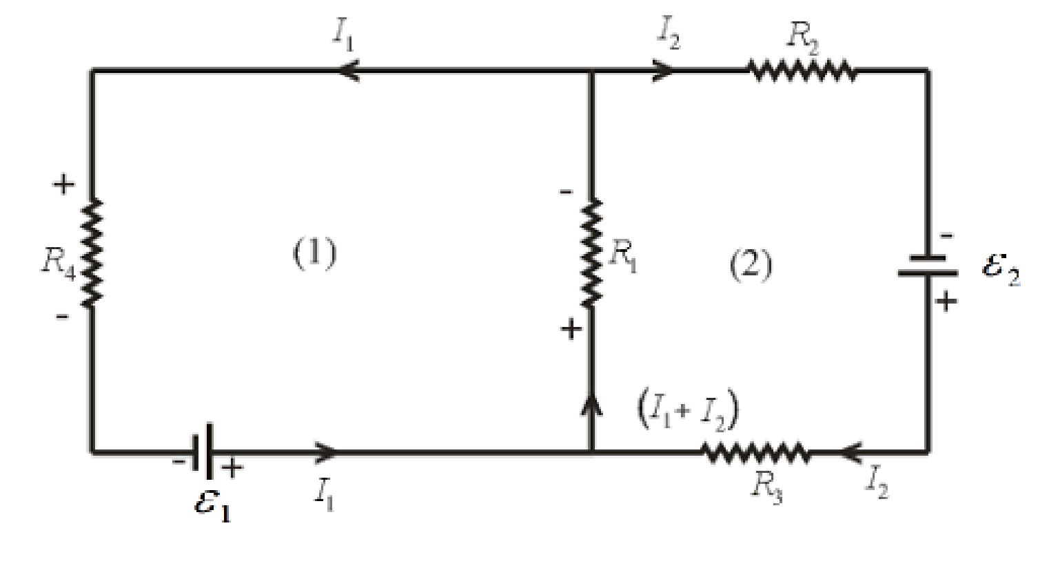
- Two ideal emf devices are connected to a set of resistors as shown in Figure P29.47. Find an expression for the emf 2 in terms of 1, R1, R2, R3, R4, and the current through R4, labeled I1.arrow_forwardA battery with = 6.00 V and no internal resistance supplies current to the circuit shown in Figure P27.9. When the double-throw switch S is open as shown in the figure, the current in the battery is 1.00 mA. When the switch is closed in position a, the current in the battery is 1.20 mA. When the switch is closed in position b, the current in the battery is 2.00 mA. Find the resistances (a) R1, (b) R2, and (c) R3. Figure P27.9 Problems 9 and 10.arrow_forwardIn the circuit of Figure P27.25, the switch S has been open for a long time. It is then suddenly closed. Determine the time constant (a) before the switch is closed and (b) after the switch is closed. (c) Let the switch be closed at t = 0. Determine the current in the switch as a function of time. Figure P27.25 Problems 25 and 26.arrow_forward
 Physics for Scientists and Engineers: Foundations...PhysicsISBN:9781133939146Author:Katz, Debora M.Publisher:Cengage Learning
 Principles of Physics: A Calculus-Based TextPhysicsISBN:9781133104261Author:Raymond A. Serway, John W. JewettPublisher:Cengage Learning
 Physics for Scientists and Engineers with Modern ...PhysicsISBN:9781337553292Author:Raymond A. Serway, John W. JewettPublisher:Cengage Learning
 Physics for Scientists and EngineersPhysicsISBN:9781337553278Author:Raymond A. Serway, John W. JewettPublisher:Cengage Learning