
Statics and Mechanics of Materials (5th Edition)
5th Edition
ISBN: 9780134382593
Author: Russell C. Hibbeler
Publisher: PEARSON
expand_more
expand_more
format_list_bulleted
Videos
Textbook Question
Chapter 5.3, Problem 1PP
In each ease, calculate the support reactions and then draw the free-body diagrams of joints A, B, and C of the truss.
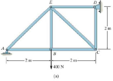
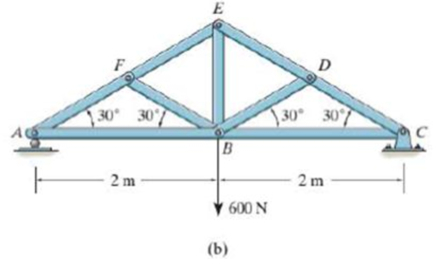
Prob. P5-1
Expert Solution & Answer
Want to see the full answer?
Check out a sample textbook solution
Students have asked these similar questions
Determine the ratio of support reaction Ra/Rc
The backhoe and its contents have a combined weight of 300 kN and center of gravity at point G. Find the resulting force in cylinder AE and linkages AB and AD, indicating whether they are in Tension or Compression. Given: L1 = 300 mm, L2 = 75 mm, L3 = 450 mm, θ = 40 °, Φ = 60 °.
Draw the free-body diagram of each object and determine the components of the support reactions.
Chapter 5 Solutions
Statics and Mechanics of Materials (5th Edition)
Ch. 5.3 - In each ease, calculate the support reactions and...Ch. 5.3 - Identify the zero-force members in each truss....Ch. 5.3 - Determine the force in each member of the truss...Ch. 5.3 - Determine the force in each member of the truss...Ch. 5.3 - Determine the force in each member of the truss...Ch. 5.3 - Determine the greatest load P that can be applied...Ch. 5.3 - Identify the zero-force members in the truss....Ch. 5.3 - Determine the force in each member of the truss...Ch. 5.3 - Determine the force in each member of the truss...Ch. 5.3 - Determine the force in each member of the truss...
Ch. 5.3 - Determine the force in each member of the truss...Ch. 5.3 - Determine the force in each member of the truss...Ch. 5.3 - Determine the force in each member of the truss,...Ch. 5.3 - Determine the force in each member of the truss,...Ch. 5.3 - Determine the force in each member of the truss...Ch. 5.3 - Determine the force in each member of the truss in...Ch. 5.3 - Members AB and BC can each support a maximum...Ch. 5.3 - Members AB and BC can each support a maximum...Ch. 5.3 - Determine the force in each member of the truss...Ch. 5.3 - If the maximum force that any member can support...Ch. 5.3 - Determine the force in each member of the truss...Ch. 5.3 - Determine the force in each member of the truss...Ch. 5.3 - Determine the force in each member of the truss...Ch. 5.3 - Determine the force in each member of the truss...Ch. 5.4 - Determine the force in members BC, CF, and FE and...Ch. 5.4 - Determine the force in members LK, KC, and CD of...Ch. 5.4 - Determine the force in members KJ, KD, and CD of...Ch. 5.4 - Determine the force in members EF, CF, and BC of...Ch. 5.4 - Determine the force in members GF, GD, and CD of...Ch. 5.4 - Determine the force in members DC, HI, and JI of...Ch. 5.4 - Determine the force in members DC, HC and HI of...Ch. 5.4 - Determine the force in members ED, EH, and GH of...Ch. 5.4 - Determine the force in members HG, HE, and DE of...Ch. 5.4 - Determine the force in members CD, HI, and CH of...Ch. 5.4 - Determine the force in members CD, CJ, KJ, and DJ...Ch. 5.4 - Prob. 22PCh. 5.4 - The Howe truss is subjected to the loading shown....Ch. 5.4 - The Howe truss is subjected to the loading shown....Ch. 5.4 - Determine the force in members EF, CF, and BC, and...Ch. 5.4 - Determine the force in members AF, BF, and BC, and...Ch. 5.4 - Prob. 27PCh. 5.4 - Determine the force in members BC, BE, and EF of...Ch. 5.4 - Prob. 29PCh. 5.4 - Determine the force in members CD, CF, and CG and...Ch. 5.4 - Determine the force developed in members FE, EB,...Ch. 5.5 - In each ease, identify any two-force members, and...Ch. 5.5 - F5-13. Determine the force P needed to hold the...Ch. 5.5 - Determine the horizontal and vertical components...Ch. 5.5 - If a 100-N force is applied to the handles of the...Ch. 5.5 - Determine the horizontal and vertical components...Ch. 5.5 - Determine the force P required to hold the 100-lb...Ch. 5.5 - In each case, determine the force P required to...Ch. 5.5 - Determine the force P required to hold the 50-kg...Ch. 5.5 - Determine the force P required to hold the 150-kg...Ch. 5.5 - Determine the reactions at the supports A, C, and...Ch. 5.5 - Determine the resultant force at pins A, B, and C...Ch. 5.5 - Determine the reactions at the supports at A, E,...Ch. 5.5 - The wall crane supports a load of 700 lb....Ch. 5.5 - The wall crane supports a load of 700 lb....Ch. 5.5 - Determine the horizontal and vertical components...Ch. 5.5 - Determine the force in members FD and DB of the...Ch. 5.5 - Determine the force that the smooth 20-kg cylinder...Ch. 5.5 - The three power lines exert the forces shown on...Ch. 5.5 - The pumping unit is used to recover oil. When the...Ch. 5.5 - Determine the force that the jaws J of the metal...Ch. 5.5 - Prob. 47PCh. 5.5 - Prob. 48PCh. 5.5 - Prob. 49PCh. 5.5 - Determine the force created in the hydraulic...Ch. 5.5 - The hydraulic crane is used to lift the 1400-lb...Ch. 5.5 - Determine force P on the cable if the spring is...Ch. 5.5 - Prob. 53PCh. 5.5 - Prob. 54PCh. 5.5 - Prob. 55PCh. 5.5 - Determine the force P on the cable if the spring...Ch. 5.5 - Prob. 57PCh. 5.5 - Prob. 58PCh. 5.5 - Prob. 59PCh. 5.5 - Prob. 60PCh. 5.5 - The platform scale consists of a combination of...Ch. 5 - All the problems solutions must include FBDs....Ch. 5 - Determine the force in each member of the truss...Ch. 5 - Determine the force in member GJ and GC of the...Ch. 5 - Determine the force in members GF, FB, and BC of...Ch. 5 - Prob. 5RPCh. 5 - Determine the horizontal and vertical components...Ch. 5 - Prob. 7RPCh. 5 - Determine the resultant forces at pins B and C on...
Knowledge Booster


Learn more about
Need a deep-dive on the concept behind this application? Look no further. Learn more about this topic, mechanical-engineering and related others by exploring similar questions and additional content below.Similar questions
- Draw the Free Body Diagramarrow_forwardDetermine the components of reaction that the ball-and-socket joint at 'A', the smooth journal bearing at 'B', and the roller support at 'C' exerted on the rod assembly in the figure.arrow_forwardDetermine the reactions at the supports of the truss structure. Set P1 = 6 kN andP2 = 9 kN.arrow_forward
- The multispan girder has two shear plate connections that act as hinges at C and D. The midspan girder CD is simply supported on the cantilevered ends of the left and right girders. Determine the forces in the hinges and the reactions at supports A, B, E, and F. Also draw the shear and moment diagram.arrow_forwardThe mobile crane is symmetrically supported by two outriggers at A and B to relieve the suspension of the vehicle on which it sits and to provide extra stability. Determine the vertical reactions at each of the two outriggers as a function of boom angle when the boom is carrying a 1.2 Mg load and the crane and truck have a combined mass of 18 Mg and the boom has a mass of 2 Mg. 0 = 45°arrow_forwardUsing Method Of Sections, Determine The Forces In Members CD And DF. 5 KN 4 KN 3 KN 2 KN |-3 M +-3m-+-3 M+-3m- 3.arrow_forward
- In the system remaining at balance like in the picture, calculate: Reaction Rd of forces inside the beams BC and AB, force P1. Impact of sphere with plain deem as perfect (reaction in the point D perpendicular to the surface). Solve exercise analytically, and with the drawings. Given: Weight of sphere Q=500N, α=30°, β=30° (Use as simplest methods as possible, excluding using lami's theorem. Its much later in my univeristy program)arrow_forwardThe truss is composed of equilateral triangles of side a = 2.4 m. The load is L = 210 N. Determine the forces in members BC and CG. The forces are positive if in tension, negative if in compression.arrow_forwardDraw the free body diagrams of (a) the whole structure, (b) members AB and BD individually, (c) the segment from A to E, (d) the segment from B to F. The forces in the free body diagrams must be named consistently.arrow_forward
- Determine the forces in members BJ, BI, CI, CH, DG, DH, and EG of the loaded truss. All triangles are 45°-45°-90°. The forces are positive if in tension, negative if in compression.arrow_forwardDraw the free body diagrams of (a) the whole structure, (b) members AB, BC and AC individually and (c) the pin at B. The forces in the free body diagrams must be named consistently.arrow_forwardDraw the free-body diagramarrow_forward
arrow_back_ios
SEE MORE QUESTIONS
arrow_forward_ios
Recommended textbooks for you
 International Edition---engineering Mechanics: St...Mechanical EngineeringISBN:9781305501607Author:Andrew Pytel And Jaan KiusalaasPublisher:CENGAGE L
International Edition---engineering Mechanics: St...
Mechanical Engineering
ISBN:9781305501607
Author:Andrew Pytel And Jaan Kiusalaas
Publisher:CENGAGE L
BEARINGS BASICS and Bearing Life for Mechanical Design in 10 Minutes!; Author: Less Boring Lectures;https://www.youtube.com/watch?v=aU4CVZo3wgk;License: Standard Youtube License