Draw the influence lines for (a) the moment at C, (b) the vertical reaction at A, and (c) the shear at C. Assume A is a fixed support. Solve this problem using the basic method of Sec. 6.1.
(a)
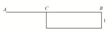
The influence lines for the moment at
Answer to Problem 6.1P
The influence line for the moment at
Explanation of Solution
Concept Used:
The unit load as
Calculation:
The following figure shows the free body diagram of the beam.
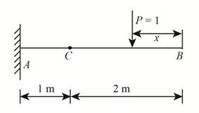
Figure-(1)
Write the equilibrium equation for the moment about point
Here, the net moment about the point
When the point load is at
Substitute,
When the point load is at
Substitute,
Conclusion:
According to the value of

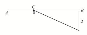
Figure-(2)
(b)
The influence line for the vertical reaction at
Answer to Problem 6.1P
The influence line for the vertical reaction at
Explanation of Solution
Concept Used:
The unit load as
Calculation:
The following figure shows the free body diagram of the beam.
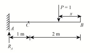
Figure-(3)
Write the equilibrium equation for the forces acting in the vertical direction.
Here, summation of the vertical forces is
Conclusion:
According to the value of the vertical reaction at

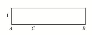
Figure-(4)
(c)
The influence line for the shear at
Answer to Problem 6.1P
The influence line for the shear at
Explanation of Solution
Concept Used:
The unit load as
Calculation:
Consider the right segment of the beam as shown in Figure-(5).
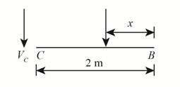
Figure-(5)
Write the equilibrium equation for the forces acting in the vertical direction.
Here, summation of the vertical forces is
Now, consider the left segment of the beam as shown in Figure-(6).
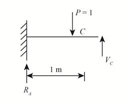
Figure-(6)
Write the equilibrium equation for the forces acting in the vertical direction.
Conclusion:
According to the values of

Figure-(7)
Want to see more full solutions like this?
Chapter 6 Solutions
Structural Analysis (10th Edition)
Additional Engineering Textbook Solutions
Foundation Design: Principles and Practices (3rd Edition)
Elementary Surveying: An Introduction To Geomatics (15th Edition)
Materials for Civil and Construction Engineers (4th Edition)
Elementary Surveying (14th Edition)
Starting Out With Visual Basic (7th Edition)
Manufacturing Engineering & Technology

- Draw the influence line for the force in member CF, and then determine the maximum compressive force that can be developed in this member due to a uniform live load of 0.8 kips/ft which is transmitted to the truss along the bottom cordarrow_forwardDetermine the maximum positive moment at C using the influence line and considering the given loads below.arrow_forwardDraw the influence lines, a) the shear at section 1-1, b) the moment at section 1-1. Please show complete solutions.arrow_forward
- For the beam shown below, determine the highest positive ordinate of the influence line for the shear at B. Thank yooouuuarrow_forwardDraw the influence line for the shear within panel cd and for the moment at e in the girder. determine (a) the maximum shear in panel cd and (b) the maximum moment in the girder at e if a single concentrated live force of 8 kn and a uniform live load of 2 kn/m can be placed on the floor beams. assume a is a pin and d is a roller.arrow_forwardDraw the influence line for the shear within panel cd and for the moment at e in the girder. determine(a) the maximum shear in panel CD and (b) the maximum moment in the girder at E if a single concentrated live force of 8 kN and a uniform live load of 2 kN/m can be placed on the floor beams. assume A is a pin and D is a roller.arrow_forward
- Determine the influence line at point B and the positive maximum moment if 60 kN/m uniform load is applied from Point D to C and concentrated load of 200kN is applied at B. Hope i'll understand with your explaination. Thank you so much :)arrow_forwardDraw the influence line for the force in (a) member CJ, and (b) member DJ.arrow_forwardDraw the influence line for (a) the force in the cable BC, (b) the vertical reaction at A, and (c) the moment at D.arrow_forward
- Construct the influence line for the vertical reaction at B of the beam shown.arrow_forwardDraw the influence line for (a) the vertical reaction at A, (b) the shear at C, and (c) the moment at C. Assume A is a roller and B is a pin.arrow_forwardDraw the influence line for the force in member CD, and then determine the maximum compressive force that can be developed in this member due to a uniform live load of 800 lb/ft which acts along the bottom cord of the truss.arrow_forward

 Structural Analysis (10th Edition)Civil EngineeringISBN:9780134610672Author:Russell C. HibbelerPublisher:PEARSON
 Principles of Foundation Engineering (MindTap Cou...Civil EngineeringISBN:9781337705028Author:Braja M. Das, Nagaratnam SivakuganPublisher:Cengage Learning
 Fundamentals of Structural AnalysisCivil EngineeringISBN:9780073398006Author:Kenneth M. Leet Emeritus, Chia-Ming Uang, Joel LanningPublisher:McGraw-Hill Education
 Traffic and Highway EngineeringCivil EngineeringISBN:9781305156241Author:Garber, Nicholas J.Publisher:Cengage Learning