
Concept explainers
Videos
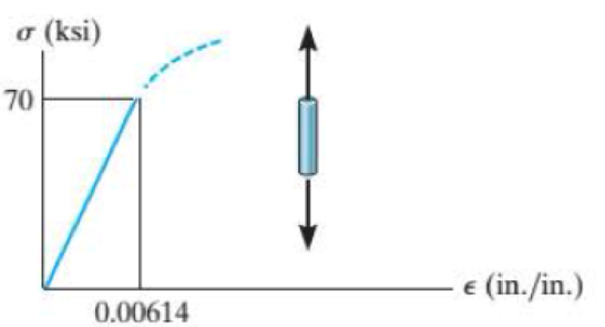
The elastic portion of the tension stress-strain diagram for an aluminum alloy is shown in the figure. The specimen used for the test has a gage length of 2 in. and a diameter of 0,5 in. When the applied load is 9 kip, the new diameter of the specimen is 0.49935 in. Calculate the shear modulus Gal for the aluminum.
Probs. R8-1/2
Find the shear modulus for an aluminum alloy
Answer to Problem 1RP
The shear modulus for an aluminum alloy is
Explanation of Solution
Given information:
Gage length is 2 in..
The diameter of the specimen is 0.5 in..
The axial load acts on the specimen is 9 kips..
The new diameter of the specimen is 0.49935 in.
Calculation:
Calculate the modulus of elasticity for aluminum
Here, the stress is
Refer the stress-strain diagram.
The value of stress is 70 ksi and the value of strain is
Substitute 70 ksi for
The expression to find the cross-sectional area of the specimen
Here, the diameter of the specimen is d.
Substitute 0.5 in. for d.
Find the value of stress when the specimen is loaded with a 9 kip load using the relation:
Here, the load is P.
Substitute 9 kip for P and
The expression to find the strain in the longitudinal or axial direction
Here, the Young’s modulus of the aluminum is E.
Substitute 45.84 ksi for
Find the strain in lateral direction
Here, the new diameter is
Substitute 0.49935 in. for
Find the Poisson’s ratio
Substitute
Calculate the modulus of rigidity for the specimen
Substitute 11,400.65 ksi for
Therefore, the shear modulus for an aluminum alloy is
Want to see more full solutions like this?
Chapter 8 Solutions
Statics and Mechanics of Materials - Modified Access


- The elastic portion of the stress–strain diagram for an aluminum alloy is shown in the figure. The specimen from which it was obtained has an original diameter of 12.7 mm and a gage length of 50.8 mm. If a load of P = 60 kN is applied to the specimen, determine its new diameter and length. Taken = 0.35.arrow_forwardThe stress-strain diagram for an aluminum alloy specimen having an original diameter of 0.5 in. and a gauge length of 2 in. is given in the figure. If the specimen is loaded until it is stressed to 60 ksi, determine the approximate amount of elastic recovery and the increase in the gage length after it is unloaded.arrow_forwardv) A delta strain gauge is attached to the member at point ‘X’ as highlighted in the figure. During a particular stage of a lifting process, strain readings are recorded as detailed. Determine the magnitude and nature of the principal stresses acting on the member at point ‘X’, the maximum shear stress, and the angle of the principal planes. Young’s Modulus of elasticity = 205 GN/m2Poisson’s ratio = 0.31arrow_forward
- The bar is made of an aluminum alloy having a stress–strain diagram that can be approximated by the straight line segments shown. Assuming that this diagram is the same for both tension and compression, determine the moment the bar will support if the maximum strain at the top and bottom fibers of the beam is Pmax = 0.05.arrow_forwardThe rigid lever arm is supported by two A-36 steel wires having the same diameter of 4 mm. If a force of P = 3 kN is applied to the handle, determine the force developed in both wires and their corresponding elongations. Consider A-36 steel as an elastic perfectly plastic material.arrow_forwardThe bar has a cross-sectional area of 0.5 in2 and is made of a material that has a stress-strain diagram that can be approximated by the two line segments. Determine the elongation of the bar due to the applied loading.arrow_forward
- The vertical steel rod has a constant diameter of 32 mm and a length of 400 mm. is hanged from a rigid fixing. A mass is gently placed onto a collar which is attached to the lower end of the rod. The strain energy stored in the steel is 0.400 x 10-³. If Esteet = 209 GPa, 1.1 Determine the gradually applied load and magnitude of the mass. 1.2 Calculate the maximum stress in the rod when gradually applied. 1.3 Determine the magnitude of the mass when the mass is suddenly applied. 1.4 Calculate the extension of the rod when suddenly applied.arrow_forwardThe strain at point A on the bracket has normal components 250x10-6 and 550x10-6 in x and y directions, respectively and shear component -600 x10-6 in x-y plane. Determine the absolute maximum shear strain in 10-6 unit.arrow_forwardA short post constructed from a hollow circular tube of aluminum supports a compressive load of 54 kips. The inner and outer diameters of the tube are d1=3.6 in. and d2=5.0 in., respectively, and its length is 40 in. The shortening of the post due to the load is measured as 0.022 in. Determine the compressive stress and strain in the post. (Disregard the weight of the post itself, and assume that the post does not buckle under the load.) 5arrow_forward
- A bar having a length of 5 in. and a cross-sectional area of 0.7 in.2 is subjected to an axial force of 8000 lb. If the bar stretches 0.002 in., determine the modulus of elasticity of the material. The material has linear elastic behavior.arrow_forwardA spherical balloon with an outer diameter of 500 mm and thickness 0.3 mm is filled with a gas. Calculate maximum permissible pressure in the balloon if the allowable normal strain at the outer surface of the balloon is O.h Assume E = 4 MPa and v = 0,45.arrow_forwardThe 200 mm long and 20 mm diameter solid circular rod is subjected to an axial force of P. P = 400 and δ = 1.6. ElasticityCalculate the modulus E and the shear modulus G. Take 0.3 Poisson's ratio.arrow_forward
 Mechanics of Materials (MindTap Course List)Mechanical EngineeringISBN:9781337093347Author:Barry J. Goodno, James M. GerePublisher:Cengage Learning