Fundamentals of Electric Circuits
6th Edition
ISBN: 9780078028229
Author: Charles K Alexander, Matthew Sadiku
Publisher: McGraw-Hill Education
bartleby

Videos

Textbook Question
Book Icon
Chapter 8, Problem 62P

Find the response vR(t) for t > 0 in the circuit of Fig. 8.107. Let R = 8 Ω, L = 2 H, and C = 125 mF.
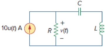
Chapter 8, Problem 62P, Find the response vR(t) for t  0 in the circuit of Fig. 8.107. Let R = 8 , L = 2 H, and C = 125 mF.

Figure 8.107

Expert Solution & Answer
Check Mark
To determine

Find the response of voltage across the resistor vR(t) for t>0 in the circuit of Figure 8.107.

Answer to Problem 62P

The response of voltage across the resistor vR(t) for t>0 is (80320te2t)u(t)V.

Explanation of Solution

Given data:

The value of resistance (R) is 8Ω.

The value of inductance (L) is 2H.

The value of capacitance (C) is 125mF.

Refer to Figure 8.107 in the textbook.

Formula used:

Write an expression to calculate the neper frequency for a series RLC circuit.

α=R2L (1)

Here,

R is the value of resistance, and

L is the value of inductance.

Write an expression to calculate the natural frequency for a series RLC circuit.

ω0=1LC (2)

Here,

C is the value of capacitance.

The three types of responses for a series RLC circuit are,

  1.         i.            When α>ω0, the system is overdamped,
  2.       ii.            When α=ω0., the system is critically damped, and
  3.     iii.            When α<ω0, the system is under damped.

Write a general expression to calculate voltage across capacitor for the step response of a series RLC circuit when the response of system is critically damped.

vC(t)=[Vs+(A1t+A2)eαt]V (3)

Here,

A1 and A2 are constants, and

Vs is the step input voltage.

Write an expression to calculate the value of step input.

u(t)={0t<01t>0

Calculation:

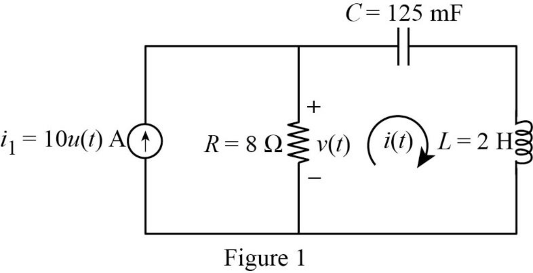
The given circuit is redrawn as shown in Figure 1.

Fundamentals of Electric Circuits, Chapter 8, Problem 62P , additional homework tip  1

For a DC circuit at steady state condition when time t=0 the capacitor acts like open circuit and the inductor acts like short circuit. The value of step input for t<0 is zero.

Since the value of step input for t<0 is zero, the current source (i1) becomes zero. The reduced diagram of Figure 1 is shown in Figure 2.

Fundamentals of Electric Circuits, Chapter 8, Problem 62P , additional homework tip  2

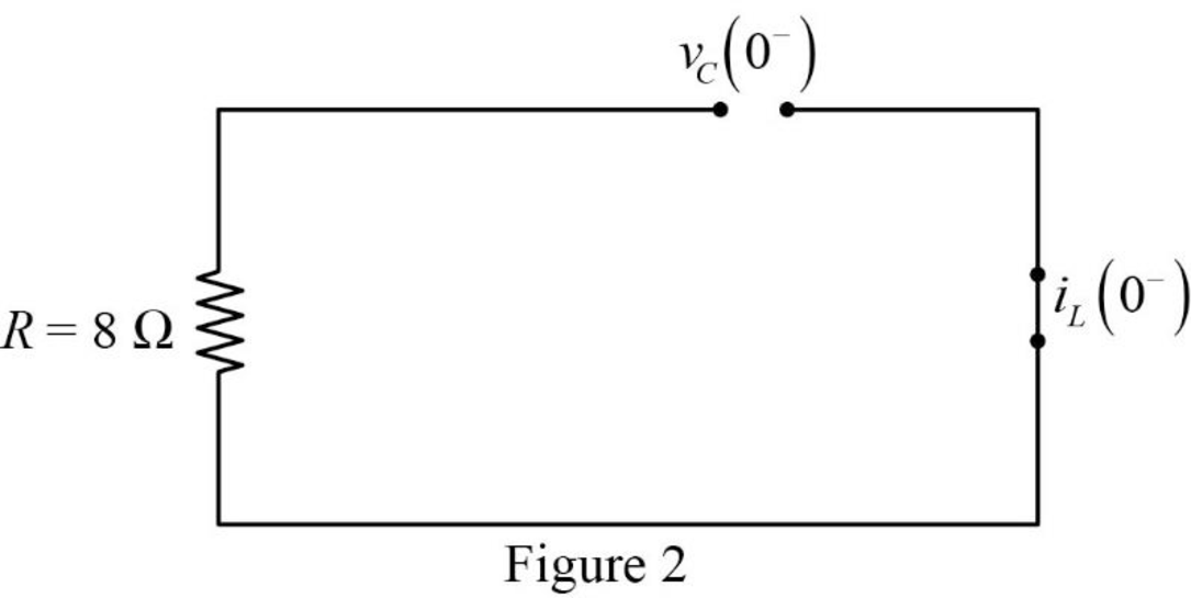
Refer to Figure 2, there is no current and voltage through the circuit. Therefore, the current through inductor and voltage across the capacitor is zero.

iL(0)=0AvC(0)=0V

The current through inductor and voltage across capacitor is always continuous so that,

i(0)=iL(0)=iL(0+)=0A

v(0)=vC(0)=vC(0+)=0V

For t>0, the value of step input is 1. Therefore, the current and voltage source becomes,

i1=10(1)A{u(t)=1fort>0}=10A

Now, the Figure 1 is reduced as shown in Figure 3.

Fundamentals of Electric Circuits, Chapter 8, Problem 62P , additional homework tip  3

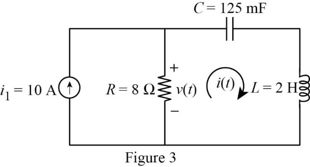
Refer to Figure 3, the voltage across the capacitor is calculated as follows,

v(t)=(10Ai(t))(8Ω) (4)

Use source transformation to convert the current source (i1) into voltage source (v1).

Write an expression to calculate the voltage source (v1).

v1=i1R (5)

Substitute 10A for i1, and 8Ω for R in equation (5) to find v1.

v1=(10A)(8Ω)=80V

The Figure 3 is reduced as shown in Figure 4.

Fundamentals of Electric Circuits, Chapter 8, Problem 62P , additional homework tip  4

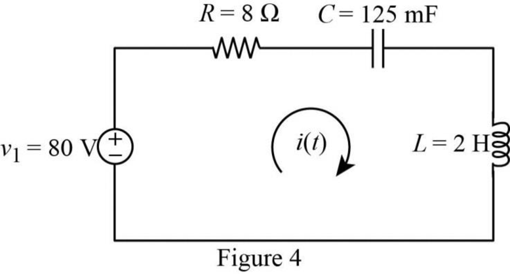
Refer to Figure 4, the circuit shows a step response of a series RLC circuit.

Substitute 8Ω for R, and 2H for L in equation (1) to find α.

α=8Ω2(2H)=8Ω2(2Ωs){1H=1Ω1s}=2Nps

Substitute 2H for L, and 125mF for C in equation (2) to find ω0.

ω0=1(2H)(125mF)=1(2H)(125×103F){1m=103}=1(2s2F)(125×103F){1H=1s21F}=2rads

Comparing the value of neper and natural frequency, the value of neper frequency is equal to the natural frequency α=ω0. Therefore, the system is critically damped.

Substitute 2 for α in equation (3) to find vC(t).

vC(t)=[Vs+(A1t+A2)e2t]V

vC(t)=[Vs+A1te2t+A2e2t]V (6)

For time t, the circuit again reaches a steady state, the capacitor acts like open circuit and the inductor acts like short circuit. Now, the Figure 4 is reduced as shown in Figure 5.

Fundamentals of Electric Circuits, Chapter 8, Problem 62P , additional homework tip  5

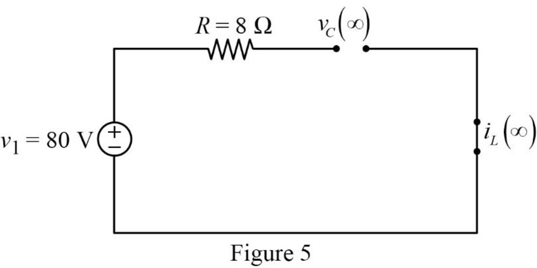
Refer to Figure 5, the circuit is open circuited so there is no current flow through inductor and voltage across the capacitor is same as the value of voltage source (v1).

vC()=80V

For a step input,

Vs=vC()=v() (7)

Substitute 80V for vC() in equation (7) to find Vs.

Vs=80V

Substitute 80V for Vs in equation (6) to find vC(t).

vC(t)=[80+A1te2t+A2e2t]V (8)

Substitute 0 for t in equation (8) to find vC(0).

vC(0)=[80+A1(0)e2(0)+A2e2(0)]V=[80+A1(0)(1)+A2(1)]V{e0=1}

vC(0)=[80+A2]V (9)

Substitute 0V for vC(0) in equation (9) to find A2.

0V=[80+A2]V80+A2=0

Simplify the above equation to find A2.

A2=80

Substitute 80 for A2 in equation (8) to find v(t).

vC(t)=[80+A1te2t80e2t]V (10)

Differentiate equation (10) with respect to t to find dvC(t)dt.

dvC(t)dt=[0+A1te2t(2)+A1(1)e2t80e2t(2)]Vs

dvC(t)dt=[2A1te2t+A1e2t+160e2t]Vs (11)

Substitute 0 for t in equation (11) to find dvC(0)dt.

dvC(0)dt=[2A1(0)e2(0)+A1e2(0)+160e2(0)]Vs=[2A1(0)(1)+A1(1)+160(1)]Vs{e0=1}

dvC(0)dt=[A1+160]Vs (12)

For a series RLC circuit, the current through resistor, inductor and capacitor are same.

i(t)=iR(t)=iL(t)=iC(t)

Write an expression to calculate the current through capacitor.

iC(t)=CdvC(t)dt (13)

Substitute i(t) for iC(t) in equation (13) to find i(t).

i(t)=CdvC(t)dt (14)

Rearrange the equation (14) to find dv(t)dt.

dvC(t)dt=i(t)C (15)

Substitute 0 for t in equation (15) to find dvC(0)dt.

dvC(0)dt=i(0)C (16)

Substitute 0A for i(0), and 125mF for C in equation (16) to find dvC(0)dt.

dvC(0)dt=0A125mF=0A125×103F=0A125×103AsV{1F=1A1s1V}=0Vs

Substitute 0Vs for dvC(0)dt in equation (12) to find A1.

0Vs=[A1+160]VsA1+160=0

Simplify the above equation to find A1.

A1=160

Substitute 160 for A1 in equation (10) to find vC(t).

vC(t)=[80160te2t80e2t]V=80[1(2t+1)e2t]u(t)V{u(t)=1fort>0}

Substitute 160 for A1 in equation (10) to find dvC(t)dt.

dvC(t)dt=[2(160)te2t+(160)e2t+160e2t]Vs=[320te2t160e2t+160e2t]Vs=[320te2t]Vs

Substitute [320te2t]Vs for dvC(t)dt, and 125mF for C in equation (14) to find i(t).

i(t)=(125mF)[320te2t]Vs=(125×103)[320te2t]FVs{1m=103}=40te2t(AsV)Vs{1F=1A1s1V}=40te2tA

Substitute 40te2tA for i(t) in equation (4) to find v(t).

v(t)=((10A)(40te2tA))(8Ω)=(1040te2t)(8)AΩ=(80320te2t)u(t)V{u(t)=1fort>0}

Refer to Figure 3, the voltage across resistor is mentioned as v(t).

Therefore,

vR(t)=v(t) (17)

Substitute (80320te2t)u(t)V for v(t) in equation (17) to find vR(t).

vR(t)=(80320te2t)u(t)V

Conclusion:

Thus, the response of voltage across resistor vR(t) for t>0 is (80320te2t)u(t)V.

Want to see more full solutions like this?

Subscribe now to access step-by-step solutions to millions of textbook problems written by subject matter experts!
Students have asked these similar questions
Show the comparison between the 2nd order damped spring model and the 2nd RLC circuit system.
1. Source-free parallel RLC circuit
For the RLC circuit given in the figure, we will find state variables such that the state equations of the system x=Ax+Bu , y=cx+du can be written in the form . Note: Accept the system output as ic.

Chapter 8 Solutions

Fundamentals of Electric Circuits

Ch. 8.8 - In the op amp circuit shown in Fig. 8.34, vs =...Ch. 8.9 - Find i(t) using PSpice for 0 t 4 s if the pulse...Ch. 8.9 - Refer to the circuit in Fig. 8.21 (see Practice...Ch. 8.10 - Draw the dual circuit of the one in Fig. 8.46.Ch. 8.10 - For the circuit in Fig. 8.50, obtain the dual...Ch. 8.11 - In Fig. 8.52, find the capacitor voltage vC for t ...Ch. 8.11 - The output of a D/A converter is shown in Fig....Ch. 8 - For the circuit in Fig. 8.58, the capacitor...Ch. 8 - For Review Questions 8.1 and 8.2. 8.2For the...Ch. 8 - When a step input is applied to a second-order...Ch. 8 - If the roots of the characteristic equation of an...Ch. 8 - In a series RLC circuit, setting R = 0 will...Ch. 8 - Prob. 6RQCh. 8 - Refer to the series RLC circuit in Fig. 8.59. What...Ch. 8 - Consider the parallel RLC circuit in Fig. 8.60....Ch. 8 - Match the circuits in Fig. 8.61 with the following...Ch. 8 - Prob. 10RQCh. 8 - For the circuit in Fig. 8.62, find: (a)i(0+) and...Ch. 8 - Using Fig. 8.63, design a problem to help other...Ch. 8 - Refer to the circuit shown in Fig. 8.64....Ch. 8 - In the circuit of Fig. 8.65, find: (a) v(0+) and...Ch. 8 - Refer to the circuit in Fig. 8.66. Determine: (a)...Ch. 8 - In the circuit of Fig. 8.67, find: (a) vR(0+) and...Ch. 8 - A series RLC circuit has R = 20 k, L = 0.2 mH, and...Ch. 8 - Design a problem to help other students better...Ch. 8 - The current in an RLC circuit is described by...Ch. 8 - The differential equation that describes the...Ch. 8 - Prob. 11PCh. 8 - If R = 50 , L = 1.5 H, what value of C will make...Ch. 8 - For the circuit in Fig. 8.68, calculate the value...Ch. 8 - The switch in Fig. 8.69 moves from position A to...Ch. 8 - The responses of a series RLC circuit are...Ch. 8 - Find i(t) for t 0 in the circuit of Fig. 8.70....Ch. 8 - In the circuit of Fig. 8.71, the switch...Ch. 8 - Find the voltage across the capacitor as a...Ch. 8 - Obtain v(t) for t 0 in the circuit of Fig. 8.73....Ch. 8 - The switch in the circuit of Fig. 8.74 has been...Ch. 8 - Calculate v(t) for t 0 in the circuit of Fig....Ch. 8 - Assuming R = 2 k, design a parallel RLC circuit...Ch. 8 - For the network in Fig. 8.76, what value of C is...Ch. 8 - The switch in Fig. 8.77 moves from position A to...Ch. 8 - Using Fig. 8.78, design a problem to help other...Ch. 8 - The step response of an RLC circuit is given by...Ch. 8 - Prob. 27PCh. 8 - A series RLC circuit is described by...Ch. 8 - Solve the following differential equations subject...Ch. 8 - Prob. 30PCh. 8 - Consider the circuit in Fig. 8.79. Find vL(0+) and...Ch. 8 - For the circuit in Fig. 8.80, find v(t) for t 0.Ch. 8 - Find v(t) for t 0 in the circuit of Fig. 8.81.Ch. 8 - Calculate i(t) for t 0 in the circuit of Fig....Ch. 8 - Using Fig. 8.83, design a problem to help other...Ch. 8 - Obtain v(t) and i(t) for t 0 in the circuit of...Ch. 8 - For the network in Fig. 8.85, solve for i(t) for t...Ch. 8 - Refer to the circuit in Fig. 8.86. Calculate i(t)...Ch. 8 - Determine v(t) for t 0 in the circuit of Fig....Ch. 8 - The switch in the circuit of Fig. 8.88 is moved...Ch. 8 - For the network in Fig. 8.89, find i(t) for t 0....Ch. 8 - Given the network in Fig. 8.90, find v(t) for t ...Ch. 8 - The switch in Fig. 8.91 is opened at t = 0 after...Ch. 8 - A series RLC circuit has the following parameters:...Ch. 8 - In the circuit of Fig. 8.92, find v(t) and i(t)...Ch. 8 - Prob. 46PCh. 8 - Find the output voltage vo(t) in the circuit of...Ch. 8 - Given the circuit in Fig. 8.95, find i(t) and v(t)...Ch. 8 - Determine i(t) for t 0 in the circuit of Fig....Ch. 8 - For the circuit in Fig. 8.97, find i(t) for t 0....Ch. 8 - Find v(t) for t 0 in the circuit of Fig. 8.98....Ch. 8 - The step response of a parallel RLC circuit is...Ch. 8 - After being open for a day, the switch in the...Ch. 8 - Using Fig. 8.100, design a problem to help other...Ch. 8 - For the circuit in Fig. 8.101, find v(t) for t 0....Ch. 8 - In the circuit of Fig. 8.102, find i(t) for t 0....Ch. 8 - Given the circuit shown in Fig. 8.103, determine...Ch. 8 - In the circuit of Fig. 8.104, the switch has been...Ch. 8 - The switch in Fig. 8.105 has been in position 1...Ch. 8 - Obtain i1 and i2 for t 0 in the circuit of Fig....Ch. 8 - For the circuit in Prob. 8.5, find i and v for t ...Ch. 8 - Find the response vR(t) for t 0 in the circuit of...Ch. 8 - For the op amp circuit in Fig. 8.108, find the...Ch. 8 - Using Fig. 8.109, design a problem to help other...Ch. 8 - Determine the differential equation for the op amp...Ch. 8 - Obtain the differential equations for vo(t) in the...Ch. 8 - In the op amp circuit of Fig. 8.112, determine...Ch. 8 - For the step function vs = u(t), use PSpice or...Ch. 8 - Given the source-free circuit in Fig. 8.114, use...Ch. 8 - For the circuit in Fig. 8.115, use PSpice or...Ch. 8 - Obtain v(t) for 0 t 4 s in the circuit of Fig....Ch. 8 - The switch in Fig. 8.117 has been in position 1...Ch. 8 - Design a problem, to be solved using PSpice or...Ch. 8 - Draw the dual of the circuit shown in Fig. 8.118.Ch. 8 - Obtain the dual of the circuit in Fig. 8.119.Ch. 8 - Find the dual of the circuii in Fig. 8.120.Ch. 8 - Draw the dual of the circuit in Fig. 8.121.Ch. 8 - An automobile airbag igniter is modeled by the...Ch. 8 - A load is modeled as a 100-mH inductor in parallel...Ch. 8 - A mechanical system is modeled by a series RLC...Ch. 8 - An oscillogram can be adequately modeled by a...Ch. 8 - The circuit in Fig. 8.123 is the electrical analog...Ch. 8 - Figure 8.124 shows a typical tunnel-diode...
Knowledge Booster
Background pattern image
Electrical Engineering
Learn more about
Need a deep-dive on the concept behind this application? Look no further. Learn more about this topic, electrical-engineering and related others by exploring similar questions and additional content below.
Similar questions
SEE MORE QUESTIONS
Recommended textbooks for you
Text book image
Introductory Circuit Analysis (13th Edition)
Electrical Engineering
ISBN:9780133923605
Author:Robert L. Boylestad
Publisher:PEARSON
Text book image
Delmar's Standard Textbook Of Electricity
Electrical Engineering
ISBN:9781337900348
Author:Stephen L. Herman
Publisher:Cengage Learning
Text book image
Programmable Logic Controllers
Electrical Engineering
ISBN:9780073373843
Author:Frank D. Petruzella
Publisher:McGraw-Hill Education
Text book image
Fundamentals of Electric Circuits
Electrical Engineering
ISBN:9780078028229
Author:Charles K Alexander, Matthew Sadiku
Publisher:McGraw-Hill Education
Text book image
Electric Circuits. (11th Edition)
Electrical Engineering
ISBN:9780134746968
Author:James W. Nilsson, Susan Riedel
Publisher:PEARSON
Text book image
Engineering Electromagnetics
Electrical Engineering
ISBN:9780078028151
Author:Hayt, William H. (william Hart), Jr, BUCK, John A.
Publisher:Mcgraw-hill Education,
L21E127 Control Systems Lecture 21 Exercise 127: State-space model of an electric circuit; Author: bioMechatronics Lab;https://www.youtube.com/watch?v=sL0LtyfNYkM;License: Standard Youtube License