What is the Pressurized pipe flow?
Pipe flow is a type of liquid flow within a closed duct or conduit. It is a branch of hydraulics and fluid mechanics.Since the flow of liquid in a pipe flow, is confined within closed conduit, it does not exert any direct atmospheric pressure on the conduit, but does exert hydraulic pressure on it. Pipes of varying diameters are linked by fittings or bends to route the fluid, valves to regulate the flow rate, and pumps to pressurize the fluid in a common piping system.
Different types of pipes
Flow sections are commonly referred to as pipe, duct, or conduit. In general, circular cross-section flow sections are called pipes (particularly for a liquid), while non-circular cross-section flow sections are called ducts (especially for gas). Tubes are used to describe pipes with a small diameter. Circular pipes convey the majority of fluids, notably liquids. This is because that pipes with such a circular cross section can sustain substantial pressure variations between the inner as well as outside without severe deformation.
Non-circular pipes are commonly employed in applications like building heating and cooling systems, where the pressure difference is minimal, manufacturing and installation costs are cheap, and ducting space is restricted.
Fluid flow in different pipes
Pipes transport the hot and cold water that we use in our houses. Hundreds of kilometers of oil and natural gas pipes carry the products. Arteries and veins carry blood throughout our bodies. Hoses transfer cooling water from an engine to radiator pipes, where it is cooled as it travels. Thermal energy is converted to circulating water in the boiler and then piped to the required places in a hydronic space heating system.
No-slip condition
The no-slip condition causes the fluid velocity in a pipe to shift from zero at the surface to a maximum in the centre of the pipe. When working with fluid flow, the average velocity stays constant in incompressible flow when the pipe's cross-sectional area is constant. In practice, however, we assess the fluid characteristics at a constant temperature. The Bernoulli equation's constant can be normalized. The total head or energy head H is a typical method, that can be expressed as
- Pressure head
- velocity head
- geopotential head
- total head
- Hydraulic head h
The convenience of dealing with constant flow rate characteristics generally outweighs the minor loss (in terms of pressure drop) in precision. A minor rise in fluid temperature occurs due to friction between fluid particles' flow rate in a pipe. The condition that the conservation of mass principle is met is used to estimate the value of the average velocity () and the pressure drop () at some stream-wise cross-section.
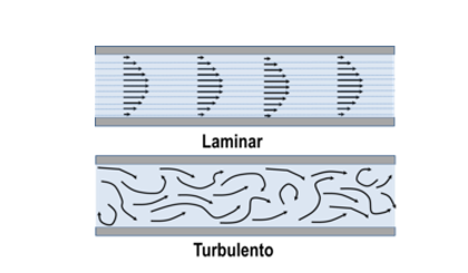
Laminar and Turbulent Flows
In the first example, the flow regime is described as laminar, with smooth streamlines and highly ordered motion, whereas in the second situation, the flow regime is described as turbulent, with velocity variations and extremely disordered motion. The transition from laminar to turbulent flow does not happen all at once; rather, it takes place over a while in which the flow alternates between laminar and turbulent flows before becoming entirely turbulent. When extremely viscous fluids like oils move via tiny pipelines or channels, laminar flow occurs.
Laminar-turbulence transition phenomenon
The influences of viscosity and gravity relative to the inertial forces of the flow determine the behavior of pipe flow. The flow can be laminar or turbulent depending on the impact of viscosity compared to inertia, as measured by the Reynolds number. As illustrated in the Moody graphic, for circular pipes of various surface roughness, pipe flow will eventually be laminar at Reynolds numbers below the critical value of roughly 2000, but turbulent flow can persist beyond the crucial value.
Some basic terms to distinguish these types
The basic terms to measurement to understand these flow types as shown below. Reynolds Number (Re) is a dimensionless number that is expressed as
As per the experimental analysis, it’s found that for pipes,
- For the laminar flow,
- For the transitional flow,
- For the turbulent flow,
Friction losses of the head in pipes
For flowing liquids, there are numerous forms of head losses such as pressure loss, etc., including friction, input, and exit losses. The primary loss is caused by the pipe's frictional resistance, which is determined by the pipe's inner roughness. Darcy's (Darcy-Weisbach equation) formula is a widely used method for estimating head loss due to friction as
Here f is the coefficient of friction (). Here d is the pipe diameter. f' is a friction factor, Q is flow rate, L is the pipe length. To calculate the head loss for a given discharge, replace [] in the last equation. Thus,
Example
A 15-kilometer-long pipe with a pipe diameter of one meter transports water at a speed of one meter per second. The pipe has a friction coefficient of 0.005. Calculate the frictional head loss?
Solution
Then for calculating the frictional head loss is as
For an incompressible fluid, the Darcy – Weisbach equation links the head loss (i.e. pressure loss) caused by friction over a given length of the pipe to the mean or average velocity of the fluid flow. The friction coefficient f is not a constant and varies depending on the pipe characteristics and the velocity of a fluid flow, but it can be calculated to a high degree of accuracy for certain flow regimes.
The study found that the Poiseuille law for laminar flow (), where Re is the Reynolds number and f is the friction factor. Using a graphic, like the Moody chart, or calculating equations, including the Colebrook-White and Hazen-Williams equation, are two methods for determining the friction coefficient f in a turbulent flow. Several empirical equations are only applicable for specific flow regimes, such as the Hazen – Williams equation, which is much easier to apply in computations. The Darcy – Weisbach equation, on the other hand, is favored because of its universality.
Secondary losses of heads in pipes
Any modification in a pipe's direction, diameter, or presence of a valve or even other fitting may result in a loss of energy or minor losses owing to the flow being disturbed.
The formula is given for estimation of Secondary Losses or minor losses of Head in Pipes is as
The velocity at the fitting's entrance, v, is the velocity. The greater velocity is typically utilized when the velocity changes downstream and upstream the segment.
Types of flow through pipe systems
Pipes in series
Consider a set of pipelines discharging water from a higher-water-level tank to a lower-water-level tank. The overall head loss between both the two tanks is equivalent to the sum of the friction losses along the pipeline, even when secondary losses are taken into consideration. The condition used to estimate the pump head as by considering three different pipe sections connected in series then
Pipes in parallel
Consider parallel pipes discharging water from a higher-water-level tank to a lower-water-level tank. Here the total head loss (HL) in between two tanks is same as the friction losses via each pipe, even if minor losses are taken into consideration. The situation was satisfied as follows. The condition used to estimates the pump head by two different pipe sections connected in parallels then
This type of flow application is mostly used in power plants and various fuel engines etc.
Context and Applications
This topic is useful for the students who are undertaking the following courses:
- Bachelors in Technology (Civil engineering, Mechanical engineering, and chemical engineering)
- Masters in Technology (Civil engineering, Mechanical engineering, and chemical engineering)
- Bachelors in Science (Physics and Chemistry)
- Masters in Science (Physics and Chemistry)
Formulas
- Bernoulli’s equation
- Reynold’s number
- Different Pipe flow conditions based on Reynold’s number
- Head losses in the pipe flow in terms of primary and secondary losses
- Head losses in the piper flow in terms of series and parallel flow system.
Practice problems
- What is the possible pipe flow in terms of Reynold’s number greater than 4000?
- Laminar flow
- Turbulent flow
- Both
- None of these
Ans. Option (b)
Explanation: When the Reynolds no. exceeds 4000, the flow is turbulent, and the fluid particles move in unusual ways.
- What is the possible pipe flow in terms of Reynold’s number less than 2000?
- Laminar flow
- Turbulent flow
- Both
- None of these
Ans. Option (a)
Explanation: As the Reynolds number is less than 2000, the flow is considered to be laminar. Viscous flow can be another name for it.
- For what type of flow is Poiseuille law used?
- Laminar flow
- Turbulent flow
- Both
- None of these
Ans. Option (a)
Explanation: Only in the case of laminar flow can Poiseuille's law is being used to estimate volume flow rate.
- What is the friction loss in each pipe for the series pipe network?
- It is the same.
- It is the sum of fiction.
- It is the difference of friction.
- None of these
Ans. Option (b)
Explanation: When a pipe line is formed by connecting pipes of various sizes in series from end to end. The sum of the localized losses plus the losses in each pipe equals the total loss.
- What is the friction loss in each pipe for the parallel pipe network?
- It is same.
- It is the sum of fiction.
- It is the difference of friction.
- None of these
Ans. Option (a)
Explanation: The friction losses in each pipe for the series pipe network will be equivalent to the same friction losses along the pipeline or the head loss will be the same is same. So if all different sized pipes are connected in parallel, then head loss between any common points is the same, hence the flows vary and the head loss is the same or the pressure difference between tanks.
Related Concepts
- Bernoulli’s equation
- Reynold’s number
- Head losses
Want more help with your civil engineering homework?
*Response times may vary by subject and question complexity. Median response time is 34 minutes for paid subscribers and may be longer for promotional offers.
Search. Solve. Succeed!
Study smarter access to millions of step-by step textbook solutions, our Q&A library, and AI powered Math Solver. Plus, you get 30 questions to ask an expert each month.
Pressurized pipe flow Homework Questions from Fellow Students
Browse our recently answered Pressurized pipe flow homework questions.
Search. Solve. Succeed!
Study smarter access to millions of step-by step textbook solutions, our Q&A library, and AI powered Math Solver. Plus, you get 30 questions to ask an expert each month.