.20 Using base values of 20 kVA and 115 volts in zone 3, rework Example 3.4.
.20 Using base values of 20 kVA and 115 volts in zone 3, rework Example 3.4.

Power System Analysis and Design (MindTap Course List)
6th Edition
ISBN:9781305632134
Author:J. Duncan Glover, Thomas Overbye, Mulukutla S. Sarma
Publisher:J. Duncan Glover, Thomas Overbye, Mulukutla S. Sarma
Chapter3: Power Transformers
Section: Chapter Questions
Problem 3.25P: Consider a single-phase electric system shown in Figure 3.33. Transformers are rated as follows:...

Related questions
Question
100%

Transcribed Image Text:3.20 Using base values of 20 kVA and 115 volts in zone 3, rework Example 3.4.
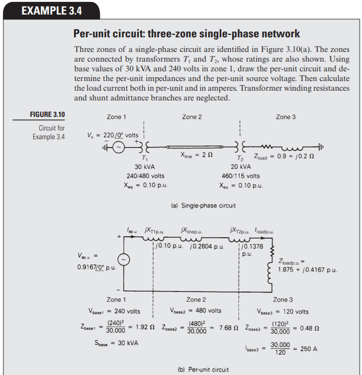
Transcribed Image Text:EXAMPLE 3.4
Per-unit circuit: three-zone single-phase network
Three zones of a single-phase circuit are identified in Figure 3.10(a). The zones
are connected by transformers T, and T, whose ratings are also shown. Using
base values of 30 kVA and 240 volts in zone 1, draw the per-unit circuit and de-
termine the per-unit impedances and the per-unit source voltage. Then calculate
the load current both in per-unit and in amperes. Transformer winding resistances
and shunt admittance branches are neglected.
FIGURE 3.10
Zone 1
Zone 2
Zone 3
Circuit for
Example 3.4
V, = 220/0° voits
muw
T, Zload = 0.9 + j0.2 N
Xiine = 2 1
30 kVA
20 kVA
240/480 volts
460/115 volts
Xeg = 0.10 p.u.
Xea = 0.10 p.u.
(a) Single-phase circuit
loou XT1p.u.
jXinep.u.
įXT2p.u. loadp.u.
|j0.1378
i p.u.
j0.10 p.u. j0.2604 p.u.
Zioadp.u. =
1.875 + j0.4167 p.u.
0.9167/0° p.u.
Zone 1
Zone 2
Zone 3
Voase = 240 volts
Vosse2 = 480 voits
Voase3 = 120 volts
Zoase
(240)2
30,000
= 1.92 N Zbase2
(480)2
30.000
- 7.68 Ω Zas3
(120)2
30,000
0.48 N
%3!
Spase
= 30 kVA
30,000
120
loase3
= 250 A
%3D
(b) Per-unit circuit
Expert Solution
This question has been solved!
Explore an expertly crafted, step-by-step solution for a thorough understanding of key concepts.

This is a popular solution!

Trending now
This is a popular solution!

Step by step
Solved in 3 steps with 4 images

Recommended textbooks for you
Power System Analysis and Design (MindTap Course …
Electrical Engineering
ISBN:
9781305632134
Author:
J. Duncan Glover, Thomas Overbye, Mulukutla S. Sarma
Publisher:
Cengage Learning
Power System Analysis and Design (MindTap Course …
Electrical Engineering
ISBN:
9781305632134
Author:
J. Duncan Glover, Thomas Overbye, Mulukutla S. Sarma
Publisher:
Cengage Learning