
Introductory Circuit Analysis (13th Edition)
13th Edition
ISBN: 9780133923605
Author: Robert L. Boylestad
Publisher: PEARSON
expand_more
expand_more
format_list_bulleted
Related questions
Concept explainers
Question
Write the differential equation for t > 0 for the
circuit of Figure P5.34
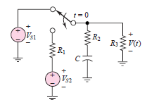

Transcribed Image Text:1= 0
R2
R3 V(t)
R1
Vs2
Expert Solution
This question has been solved!
Explore an expertly crafted, step-by-step solution for a thorough understanding of key concepts.

Step by stepSolved in 5 steps with 9 images

Knowledge Booster


Learn more about
Need a deep-dive on the concept behind this application? Look no further. Learn more about this topic, electrical-engineering and related others by exploring similar questions and additional content below.Similar questions
- 6 At t< 0, the circuit shown in Figure P5.66 is at steady state, and the voltage across the capacitor is +7 V. The switch is changed as shown at t= 0, and Vs = 12 V C= 3,300 µF R = 9.1 k2 R = 4.3 k2 R3 = 4.3 k2 L= 16 mH Determine the initial voltage across R2 just after the switch is changed. t=0 Le )V½ R R 2 R3 ww-arrow_forward7 Steady-state conditions exist in the circuit shown in Figure P5.27 at t < 0. The switch is closed at t = 0. V = 12 V R = 0.68 k2 R = 2.2 k2 R = 1.8 k2 C= 0.47 µF Determine the current through the capacitor at t = 0+, just after the switch is closed. ww. idt) R. t= 0 R1 Ry ww-arrow_forwardDetermine the initial and final conditions for thecircuit of Figure P5.49arrow_forward
- Determine the initial and final conditions for thecircuit of Figure P5.29.arrow_forwardWrite the differential equation for t > 0 for thecircuit of Figure P5.52.arrow_forwardRefer to Figure P5.11. Find the value of K₁ and K₂ that will result in a step response with a peak value of 1.5 sec. and a settling time of 3 sec. R(s) K₁ 30 s(s+2) K2s C(s)arrow_forward
- The switch in the circuit of Figure P5.58 opens att = 0. It closes at t = 10 seconds.a. What is the time constant for 9 < t < 10 s?b. What is the time constant for t > 10 s?arrow_forwardWrite the differential equation for t > 0 for thecircuit of Figure P5.41arrow_forwardAn open circuit is composed of a capacitor with capacitance C and an inductorwith inductance L. The capacitor is charged to a voltage V and at time t = 0 the circuit isclosed. Find the current as a function of time, I(t).arrow_forward
- 8 For t > 0, the circuit shown in Figure P5.22 is at steady state. The switch is changed as shown at t = 0. Vsi = 35 V C = 11 µF Vsz = 130 V R = 17 k2 R = 7 k2 R = 23 k2 Determine the time constant of the circuit for t> 0.arrow_forwardNAALINE ersity Book Q5. An inductor has a negligible resistance and an inductance of 200mH and is connected in series with a 1 k resistor to a 24V d.c. supply. Determine the time constant of the circuit and the steady state value of the current flowing in the circuit. Find (a) the current flowing in the circuit at a time equal to one time constant, (b) the voltage drop across the inductor at a time equal to two time constants and (c) the voltage drop across the resistor after a time equal to three time constants.arrow_forward1 Just before the switch is opened at t = 0 in Figure P5.21, the current through the inductor is 1.70 mA in the direction shown. Vs = 12 V L = 0.9 mH R = 6 k2 R2 = 6 k2 R = 3 k2 Determine the time constant of the circuit for t > 0.arrow_forward
arrow_back_ios
arrow_forward_ios
Recommended textbooks for you
- Introductory Circuit Analysis (13th Edition)Electrical EngineeringISBN:9780133923605Author:Robert L. BoylestadPublisher:PEARSON
 Delmar's Standard Textbook Of ElectricityElectrical EngineeringISBN:9781337900348Author:Stephen L. HermanPublisher:Cengage Learning
 Programmable Logic ControllersElectrical EngineeringISBN:9780073373843Author:Frank D. PetruzellaPublisher:McGraw-Hill Education
  Fundamentals of Electric CircuitsElectrical EngineeringISBN:9780078028229Author:Charles K Alexander, Matthew SadikuPublisher:McGraw-Hill Education
 Electric Circuits. (11th Edition)Electrical EngineeringISBN:9780134746968Author:James W. Nilsson, Susan RiedelPublisher:PEARSON
 Engineering ElectromagneticsElectrical EngineeringISBN:9780078028151Author:Hayt, William H. (william Hart), Jr, BUCK, John A.Publisher:Mcgraw-hill Education,
Introductory Circuit Analysis (13th Edition)
Electrical Engineering
ISBN:9780133923605
Author:Robert L. Boylestad
Publisher:PEARSON
Delmar's Standard Textbook Of Electricity
Electrical Engineering
ISBN:9781337900348
Author:Stephen L. Herman
Publisher:Cengage Learning
Programmable Logic Controllers
Electrical Engineering
ISBN:9780073373843
Author:Frank D. Petruzella
Publisher:McGraw-Hill Education
Fundamentals of Electric Circuits
Electrical Engineering
ISBN:9780078028229
Author:Charles K Alexander, Matthew Sadiku
Publisher:McGraw-Hill Education
Electric Circuits. (11th Edition)
Electrical Engineering
ISBN:9780134746968
Author:James W. Nilsson, Susan Riedel
Publisher:PEARSON
Engineering Electromagnetics
Electrical Engineering
ISBN:9780078028151
Author:Hayt, William H. (william Hart), Jr, BUCK, John A.
Publisher:Mcgraw-hill Education,