
Electric Motor Control
10th Edition
ISBN: 9781133702818
Author: Herman
Publisher: CENGAGE L
expand_more
expand_more
format_list_bulleted
Related questions
Question
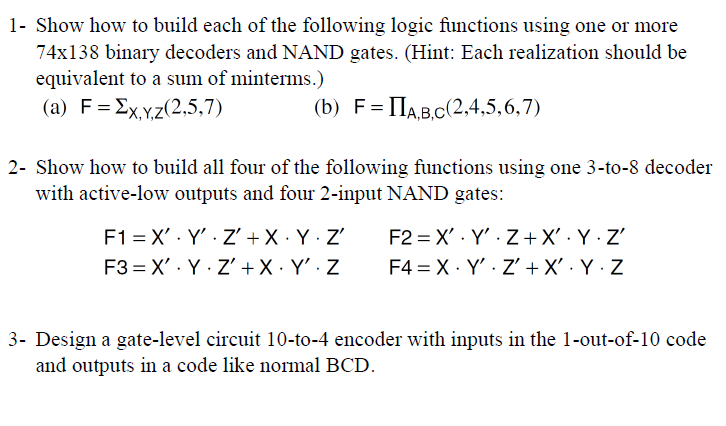

Transcribed Image Text:1- Show how to build each of the following logic functions using one or more
74x138 binary decoders and NAND gates. (Hint: Each realization should be
equivalent to a sum of minterms.)
(a) FΣx,y,z(2,5,7)
(b) FIA,B,C(2,4,5,6,7)
2- Show how to build all four of the following functions using one 3-to-8 decoder
with active-low outputs and four 2-input NAND gates:
F1 X'Y' Z' + X. Y. Z'
F2
.
X Y Z+X'. Y. Z'
F3
X Y Z' + X. Y'. Z
F4
X Y' Z' + X' . Y. Z
3- Design a gate-level circuit 10-to-4 encoder with inputs in the 1-out-of-10 code
and outputs in a code like normal BCD.
SAVE
AI-Generated Solution
info
AI-generated content may present inaccurate or offensive content that does not represent bartleby’s views.
Unlock instant AI solutions
Tap the button
to generate a solution
to generate a solution
Click the button to generate
a solution
a solution
Knowledge Booster

Similar questions
- Nonearrow_forwardT: Answer thne f. questions: 1) The hexadecimal number ´Al' has the decimal value equivalent to (A) 80 (B) 161 (C) 100 (D) 101 2) The output of a logic gate is 0 when all its inputs are logic 1. The logic is either (A) a NAND or an EX-OR (B) an OR or an EX-NOR (C) an AND or an EX-OR (D) an NOR or an EX-NOR 3) The Gray code of the Binary number 1100111 is (A) 1011011 (B) 1010100 (C) 1001001 (D) 101101 4) When simplified with Boollean Algebra (a+b)(a+c) simplifies to (A) a (B) a+a(b+c) (C) a(1+bc) (D) a+bc 5) -31 is represented as a sign Binary number ( using Sign-magnitude form ) equal to (A) 00011111 (B) 10101001 (C) 01110010 (D) 00101101 6) The Binary number 110111 is equivalent to decimal number (A) 25 (B) 55 (C) 26 (D) 34 7) With 4 bit, what the range of decimal values if the number is 2's complement signed number. (A) -32 to +31 (B) -2 to +1 (C) -8 to +7 (D) None of thesearrow_forwardDesign counter that counts from 00 to 59, using the IC 74LS90 ripple counter and use two 7 segment display to display the result count. You can also use 7447 binary to 7-segment Display Decoder in logicworks.arrow_forward
- Digital logic design Solve it with drawing and simulation lab I need them both to have the full solution. And thanks Design counter that counts from 00 to 59, using the IC 74LS90 ripple counter and use two 7 segment display to display the result count. You can also use 7447 binary to 7-segment Display Decoder.arrow_forward1. Gray code to Binary converter: Gray code is one of the codes used in digital systems. It has the advantage over binary numbers that only one bit in the code word changes when going from one number to the next. (See Table 1). Design a combinational circuit with 4 inputs and 4 outputs that converts a four- bit gray code number into an equivalent four-bit Binary number. Use Karnaugh map technique for simplification. Use LogicWorks for pre-lab demonstrations. Select the library "7400dev.clf* in the Parts Palette and then select the XOR chip 74-86. This would give you a set of 4 XOR's as shown in Fig. 1, just like the hardware chip 74-86. You could use as many as needed from these XOR gates in your design. Get back to ALL LIBRARIES and select switches for the inputs and Binary Probes as indicators of the outputs. Verify your design in the pre-Lab. During the Lab construct the circuit and verify its operations.arrow_forward3. Discussion: 1. Convert the gray code 01011001 to decimal number and show your work. 2. Convert the gray code 00101101 to binary number and show your work. 3. Design a 8-bit binary to gray code conversion circuit using logic gates and verify your design. 4. Design a 8-bit gray to binary code conversion circuit using logic gates and verify your design.arrow_forward
- ‘arrow_forwardDesign the following combinational logic circuit with a four-bit input and a three-bit output. The input represents two unsigned 2-bit numbers: A1 A0 and B1 B0. The output C2 C1.C0 is the result of the integer binary division A1 A0/B1 B0 rounded down to three bits. The 3-bit output has a 2-bit unsigned whole part C2 C1 and a fraction part CO. The weight of the fraction bit CO is 21. Note the quotient should be rounded down, i.e. the division 01/11 should give the outputs 00.0 (1/3 rounded down to 0) not 00.1 (1/3 rounded up to 0.5). A result of infinity should be represented as 11.1. A minimal logic implementation is not required. (Hint: start by producing a truth table of your design).arrow_forwarda) Design a single-digit decade counter that counts from 0 to 9 and repeats. The single-digit decade counter should be built by a cascaded synchronous binary counter (74LS163) and other basic logic gates. Simulate thecomplete counter circuit by OrCAD and PSPICE. Capture the circuit schematic and the simulated waveform.(Define the simulation timings for at least one full counting cycle from 0 to 9 and back to 0.)(Hint: Use the DigClock input from the SOURCE as shown below and setup the CLK ONTIME and OFFTIME accordingly for the clock source.)arrow_forward
- Please answer this question with as much details possible, so I can understand. This is for Electrical Engineering.arrow_forwardAnswer the D, E and F partarrow_forwardQ4 A-Design Parallel load/Shift right 4 bit register with LD/SR signal. If LD/SR =1 then register parallel load from D3D2DIDO inputs. If LD/SR =0 then it shifts right. Use standard logic gates and D F-F.arrow_forward
arrow_back_ios
SEE MORE QUESTIONS
arrow_forward_ios
Recommended textbooks for you