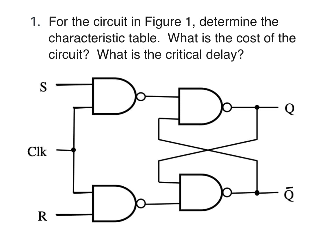
1. For the circuit in Figure 1, determine the characteristic table. What is the cost of the circuit? What is the critical delay? S Q Clk R


Q: Design an appropriate combinational circuit that implements a digital system with the following…
A: Design a combinational circuit which take 4bit input and it has 7 outputs to which connect with the…
Q: Draw the circuit and obtain the truth table of the VHDL module below module SAM(a, b, c, M, S);…
A: We need to draw the circuit and obtain the truth table of the given VHDL module.
Q: For the full-wave rectifier circuit shown in Fig. below, assume ideal diodes Find : (i) d.c. output…
A:
Q: a) Draw the graphic symbol (block diagram) of SR Flip Flop on page. Mention/label all inputs and…
A: GIVEN: a) Draw the graphical symbol of SR flip flop. b) Draw the characteristic table c) Draw the…
Q: QUESTION Using basic gates ONLY, simplify and convert the circuit below. Show all your workings. D-D
A:
Q: If R = 200 Ω and C = 20 μF in the circuit in the figure, what is the time constant of the circuit in…
A: Time constant= R×C = 200 × 20 × 10^-6 = 4 ms
Q: A majority circuit is a combinational circuit whose output is equal to 1 if the input variables have…
A: Majority circuit: Truth Table: x y z f 0 0 0 0 0 0 1 0 0 1 0 0 0 1 1 1 1 0 0 0 1 0 1 1 1 1 0 1 1 1…
Q: Determine the worst case delay of CMOS circuit with the expression F=((A.C)+B).(A’.C’) driving 8…
A: Given: Determine the worst case delay of CMOS circuit with the expression F=((A.C)+B).(A’.C’)…
Q: Write the Boolean equation
A: first three parts will be amswered Boolean equation: a) W = (A.B) +C +(C.D) = A.B + C(1+D)…
Q: what is the concept of the clipper circuit? And give an example of the (unbiased series clipper…
A: The term "clipper circuit" refers to a circuit that eliminates or clips off a segment of an input…
Q: a) Calculate parameters E, and R, of the Thevenin equivalent circuit at the load terminals…
A: Please could I have the written solution for this question. fullscreen fullscreen
Q: Calculate the operating frequency of the LR circuit in which: R= 100 N, L=50 H, Z=6002.
A: Answer:
Q: Find the state table for the circuit
A: Total number of States = 6 Thus number of state bits required = 3 Let A=000 B=001 C=010 D=011 E=100…
Q: 16 line to 1 line MUX (data selector) 1) Truth table 2) Circuit diagram Note use gate for circuit…
A: Given: 16 line to 1 line MUX (data selector) 1) Truth table 2) Circuit diagram Note use gate for…
Q: : For the circuit given in Fig.2, determine the output waveforms ( X, Y, and z) with inputs…
A: I have provided a solution in step 2.
Q: A' A B' B Clk Clk T T Clock
A: The given circuit is Mod 3 counter using T flip flop. Which repeatedly count 0,1,2,0,1,2,... State…
Q: Problem: Draw the RC equivalent circuit for the logic function below and calculate the falling and…
A: Logical RC equivalent circuit.......
Q: Question 1 : Consider the following combinational circuit (3 inputs: A, B and C- 2 outputs: X and Y)
A:
Q: Assignment_5: Design a synchronous 2-bit ring counter with illegal state recovery circuitry. Analyze…
A: Ring Counter - It is built with the help of flip flop, and named as ring counter because output of…
Q: onstruct the state diagram, primitive flow table and reduced flow table for a fundamental mode…
A: ANSWER: Primitive Flow Table: A primitive flow table is a flow table with just one stable absolute…
Q: Show the FF-input equations, state table and state diagram of each circui
A: SUMMARY: - Hence, we discussed all the points.
Q: 1. Define the following terms: a) combinational circuit: 5) sequential circuit: E) excitation table:…
A: In digital logic, there are some important key terms that must be cleared before deep dive. E.g…
Q: For the circuit in Figure 07, draw the waveforms at the numbered points in the proper relationship…
A: For the circuit in Figure 07, draw the waveforms at the numbered points in the proper…
Q: 1. For the circuit shown in the figure, assume the inputs are Add/Subt = 1, A = 1111, and B = 1100.…
A: 0
Q: Given the asynchronous circuit, determine the map Q1, Q2, Z, transition table, and flow table. X…
A: check the below answer
Q: • Derive State Table and Draw State Diagram of the given clocked sequential Circuit CIk R т B Clk
A:
Q: -In CMOS gates, what occurs when the frequency of the input signal increas A) The power dissipation…
A: Question: In CMOS gates, what occurs when the frequency of the input signal increases: A) The power…
Q: As seen in Table 1, you are given ICs with a restricted number of units. Design a 4-bit multiplier…
A: Answer DesignThe control unit, the accumulator/shift register, and the 4-bit adder are the three…
Q: QI) Design a combinational circuit with three inputs, A, B and Outputs, X,Y and Z. when the binary…
A: Truth Table is A B C X Y Z 0 0 0 0 1 0 0 0 1 0 1 1 0 1 0 1 0 0 0 1 1 1 0 1 1 0 0 1 1 0…
Q: A R T CLK Reset
A: Given The answer is given below Input equations:
Q: If the diode is 1. Sketch the circuit. forward-biased connected then: 2. Explain the principle…
A: When the external voltage is applied across the P-N junction diode, this is known as forward bias or…
Q: The circuit below has a 2-to-4 decoder with active high outputs connected to a 4-to-1 MUX. Derive an…
A: Decoder:A binary code of n bits is capable of representing up to 2^n distinct elements of coded…
Q: For the circuit shown below, find the value of V. 741 Vo 1 mA Color code for resistors: 12 345 6 789…
A: IC 741 is an operational amplifier integrated circuit which have a wide range of application in…
Q: From the given circuit, derive the simplified NOT-OR-AND circuit and identify the TTL ICs in the…
A: The simplified NOT-OR-AND circuit The TTL ICs are NAND and NOR gate. Here 4 TTL ICs was being used…
Q: a) Write the truth table and logical expression for a two-input NAND gate. b) Draw the IC pin…
A: I have provided both the answers in step 2.
Q: 7. Determine Vo for the circuit in figure below, with 10v on both inputs. Si D D A 01 8. Determine…
A:
Q: Find the Boolean function implemented by the CMOS gate circuit whose bar diagram is given below.
A: The correct answer is option A) Reason: The three trans are in parallel (A, B, C) and the trans D…
Q: DISCUSSION: 1. Explain why a series RL circuit with high inductance has a slow response?
A: As it was not stated which question to be answered, I'm answering the question of the discussion…
Q: ( /For the circuit shown below, determine the value of Vo, using Nodal analysis. ww 12 V
A: To determine the value of vo
Q: Q4:(A) Find The ASM chart for the circuit shown below A 1\0 1\0 1\0 0\0 0\0 1\0 B 1\0 0\1 0\0 D 0\0…
A: Given the state diagram we have to draw the ASM chart for the circuit shown below.
Q: Q4. A combinational circuit has 3 outputs F1, F2 and F3 F1 = xy Z+ xz F2 = x y Z+x y F3 = x y z + xy…
A: Introduction: A decoder is a digital circuit that can produce 2^n output lines by taking 'n' input…
Q: Construct the state table for the circuit
A: when previous state y2y1 = 00 and x=0 we have input to the rom is 000 = 0 hence output of the rom is…
Q: For the system of the given figure, the damping ratio of the closed loop pole is 4 C(s) s(s+2)…
A: Hello student Greetings Hope you are doing great I will try my best to answer your question. Thank…
Q: Problem 1. Draw the waveforms of Q0, Q1, Q2 (all initialized to zero) What is the countering…
A:
Q: Problem 5: Explain why the circuit in Figure 4 is a 4-to-1 MUX. 注D Vo V1 f W2 En Figure 4
A: According to the information given:- We have to explain why the circuit is a 4 to 1 MUX.
Q: ii) For the circuit shown in figure (Q5-ii), deduce the state diagram for the circuit. 10₂ De D₁ D₂…
A: Given circuit is a sequential circuit which contains three D flip flops. For each flipflop, clock…
Q: Compare Combinational digital circuit with Sequential digital circuit. Explain about D latch with…
A: Both the sequential and combinational circuits are the most widely used ones in the arena of digital…
Q: Using NAND gates, one 3-8 decoder, and 1 2-1 MUX, design a combination circuit with two outputs…
A:
Q: F1 = xyZ + xz F2 = x y Z+Xy F3 = xỹ z + xy
A: F1=x'y'z'+xz = x'y'z'+xz(y+y') = x'y'z'+xyz+xy'z = x'y'z'+xy'z+xyz = Σ (0,5,7) F2=xy'z'+x'y =…


Trending now
This is a popular solution!

Step by step
Solved in 3 steps


- Draw the circuit diagram to output F given in the expression above by referring to schematics for 2-2) and 2-3). Use the space below to draw both the IC with pin assignments and a circuit schematic. Using a single 7400 IC construct a circuit to output the following Boolean function: F = AB + CDonstruct the state diagram, primitive flow table and reduced flow table for a fundamental mode circuit whose behaviour is as follows: Initial condition: Both the inputs and outputs are zero For x1 = 1 and x2 = 0; output (z) = 1 x1 = 0 and x2 = 1; output (z) = 0 x1x2 = 00 and x1x2 = 11; z = previous outpuA medium scale Digital Circuit needs to be implemented on an ASIC. Study and list out any two points highlighting the parameters and performance indicators when the selection of the ASIC goes in favor for a CPLD instead of an FPGA.
- Design the simplest circuit that has three inputs, a, b, and c, which returns an output value of 1 whenever g and b are complements of each other or b and c are complements of each other, otherwise the output is 0. Realize the circuit using 4input , 3output PALBriefly describe what is the time complexity of circuit SAT? Please show written work with answer!!1. Design and implement a circuit using positive edge triggered DFFs that generates a pulse (p = 1) on the 2nd, 3rd, 5th, and 7th clock cycles after initialization. The sequence should repeat every 8 clock pulses. Include an asynchronous reset signal. 1.1 Implement your design in Verilog (behavioral)
- need circuitry design for this truth table ?How does eulerian and hamiltonian circuit correlates in real life? and why is it important?1. Explain the importance of combinational and sequesntion logic circuits, as well as having in Designing of a Sensor for Monitoring Indoor Venue Capacity. 2. Why does Logic Gates IC's and K-Maps important in Designing of a Sensor for Monitoring Indoor Venue Capacity.