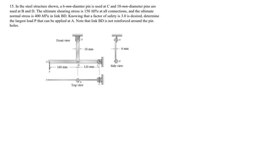
15. In the steel structure shown, a 6-mm-diamter pin is used at C and 10-mm-diameter pins are used at B and D. The ultimate shearing stress is 150 MPa at all connections, and the ultimate normal stress is 400 MPa in link BD. Knowing that a factor of safety is 3.0 is desired, determine the largest load P that can be applied at A. Note that link BD is not reinforced around the pin holes. Front view 18 mm 6 mm 160 mm 120 mm Side view Top view
15. In the steel structure shown, a 6-mm-diamter pin is used at C and 10-mm-diameter pins are used at B and D. The ultimate shearing stress is 150 MPa at all connections, and the ultimate normal stress is 400 MPa in link BD. Knowing that a factor of safety is 3.0 is desired, determine the largest load P that can be applied at A. Note that link BD is not reinforced around the pin holes. Front view 18 mm 6 mm 160 mm 120 mm Side view Top view

Elements Of Electromagnetics
7th Edition
ISBN:9780190698614
Author:Sadiku, Matthew N. O.
Publisher:Sadiku, Matthew N. O.
ChapterMA: Math Assessment
Section: Chapter Questions
Problem 1.1MA

Related questions
Question
Transcribed Image Text:15. In the steel structure shown, a 6-mm-diamter pin is used at C and 10-mm-diameter pins are
used at B and D. The ultimate shearing stress is 150 MPa at all connections, and the ultimate
normal stress is 400 MPa in link BD. Knowing that a factor of safety is 3.0 is desired, determine
the largest loadP that can be applied at A. Note that link BD is not reinforced around the pin
holes.
Front view
D.
18 mm
6 mm
160 mm
120 mm
Side view
Top view
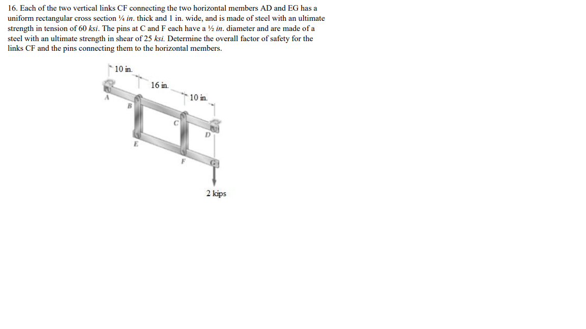
Transcribed Image Text:16. Each of the two vertical links CF connecting the two horizontal members AD and EG has a
uniform rectangular cross section ¼ in. thick and 1 in. wide, and is made of steel with an ultimate
strength in tension of 60 ksi. The pins at C and F each have a ½ in. diameter and are made of a
steel with an ultimate strength in shear of 25 ksi. Determine the overall factor of safety for the
links CF and the pins connecting them to the horizontal members.
10 in.
16 in.
10 in.
2 kips
Expert Solution
This question has been solved!
Explore an expertly crafted, step-by-step solution for a thorough understanding of key concepts.

This is a popular solution!

Trending now
This is a popular solution!

Step by step
Solved in 6 steps with 1 images

Knowledge Booster


Learn more about
Need a deep-dive on the concept behind this application? Look no further. Learn more about this topic, mechanical-engineering and related others by exploring similar questions and additional content below.Recommended textbooks for you
Elements Of Electromagnetics
Mechanical Engineering
ISBN:
9780190698614
Author:
Sadiku, Matthew N. O.
Publisher:
Oxford University Press

Mechanics of Materials (10th Edition)
Mechanical Engineering
ISBN:
9780134319650
Author:
Russell C. Hibbeler
Publisher:
PEARSON

Thermodynamics: An Engineering Approach
Mechanical Engineering
ISBN:
9781259822674
Author:
Yunus A. Cengel Dr., Michael A. Boles
Publisher:
McGraw-Hill Education
Elements Of Electromagnetics
Mechanical Engineering
ISBN:
9780190698614
Author:
Sadiku, Matthew N. O.
Publisher:
Oxford University Press
Mechanics of Materials (10th Edition)
Mechanical Engineering
ISBN:
9780134319650
Author:
Russell C. Hibbeler
Publisher:
PEARSON
Thermodynamics: An Engineering Approach
Mechanical Engineering
ISBN:
9781259822674
Author:
Yunus A. Cengel Dr., Michael A. Boles
Publisher:
McGraw-Hill Education

Control Systems Engineering
Mechanical Engineering
ISBN:
9781118170519
Author:
Norman S. Nise
Publisher:
WILEY

Mechanics of Materials (MindTap Course List)
Mechanical Engineering
ISBN:
9781337093347
Author:
Barry J. Goodno, James M. Gere
Publisher:
Cengage Learning

Engineering Mechanics: Statics
Mechanical Engineering
ISBN:
9781118807330
Author:
James L. Meriam, L. G. Kraige, J. N. Bolton
Publisher:
WILEY