
Introductory Circuit Analysis (13th Edition)
13th Edition
ISBN: 9780133923605
Author: Robert L. Boylestad
Publisher: PEARSON
expand_more
expand_more
format_list_bulleted
Related questions
Question
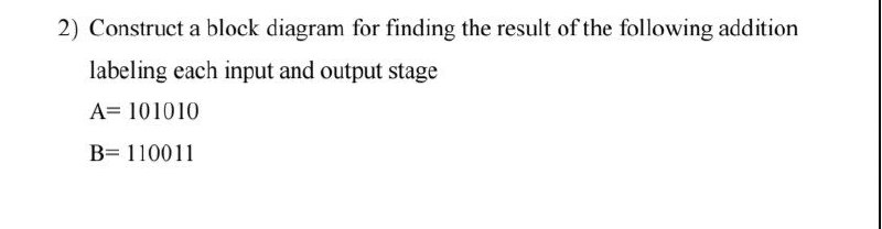

Transcribed Image Text:2) Construct a block diagram for finding the result of the following addition
labeling each input and output stage
A=101010
B=110011
Expert Solution
This question has been solved!
Explore an expertly crafted, step-by-step solution for a thorough understanding of key concepts.

Step by stepSolved in 2 steps with 2 images

Knowledge Booster

Similar questions
- The data-input and data-select waveforms in Figure 7 are applied to the multiplexer. Determine the output waveform F in relation to the inputs.arrow_forwardQ 1. Determine the output voltage of the Digital-to-Analog Converter (DAC) in Figure 1(a) and plot it in Figure 1(c). The sequence of the four digit binary codes represented by the waveforms in Figure 1(b) are applied to the inputs. A high level is a binary 1and a low level is a binary 0. The least significant binary digit is Do. Do o D₁ 0- 200 ΚΩ www D₂ 0 100 ΚΩ www 50 ΚΩ www 25 ΚΩ D3 0 M 0 -0.25 -0.50 -0.75 -1.00 -1.25 -1.50 -1.75 -2.00 -2.25 -2.50 -2.75 -3.00 -3.25 -3.50 -3.75 (a) Vout (V) R₁ 10 ΚΩ o Vout +5 V Do 0 +5 V D₁ 0 +5 V 0 +5 V 0 D₂ D3 0 1 2 3 4 5 6 7 8 9 10 11 12 13 14 15 non (c) Figure 1 I 0000 0001 0010 0011 0100 0101 0110 0111 1000 1001 1010 1011 1100 1101 1110 1111 ||||| (b) Binary inputarrow_forward11. Determine and draw the resulting output waveform in relation to the inputs for following circuit block. Assume Q starts low. SO R0 Q S D R earrow_forward
- Listen A 12 bit DAC has a lower reference voltage of OV and an upper reference voltage of 3.0V What is the output voltage for a code of Ox74B? Round the answer to 2 decimal places. a) 1.37V Ob) 1.50V c) 1.60V O d) 1.12Varrow_forward(Asterisked problems are associated with optional sections.) 1. Determine the output of each of the following circuits, assuming that the upper input is 1 and the lower input is 0. What would be the output when the upper input is 0 and the lower input is 1? a. b. C. D D nia 00arrow_forward3. XMM1 is an ammeter and its reading is OA for the whole input signal cycle. What could be wrong in the circuit? Explain. XMM1 Q1 R1 1kQ D1 V2 1kHz 5V V1 12V L1 1mHarrow_forward
- 1. XMM1 is a voltmeter and its reading is 0V at the whole input signal cycle. What could be wrong in the circuit? Explain. XMM1 D1 L1 1mH R1 1kQ 5V C1 Q1 V1 IRF2805S :1pF 12V V2 1kHz 5Varrow_forwardReset WED W=O W =l EhD DII W=0 Derive the following state-table Present state Next state output z2zlz0 W=0 W=1 A 000 B 001 C 010 D 011 E 100arrow_forwardShow the sketch with all the detailsarrow_forward
- Question 01: If the waveforms in Figure Q-01 are applied to an active-HIGH S-R latch, draw the resulting Q output waveform in relation to the inputs. Assume that Q starts LOW. S R Figure Q-01. as R Qarrow_forwardWhat is the output (in decimal format) of a 10-bit unipolar A/D converter for the input of 100mV? Assume that the converter uses 5V as a reference voltage for conversion purposes. The converter input range is 0V to 5V. Round your answer to the nearest integer value.arrow_forwardbuild an inverting summing amplifier with 2 inputs: a 1 V DC signal anda sine wave with an amplitude of 2 V and 1 kHz frequency.V Simulate for 2 msecarrow_forward
arrow_back_ios
SEE MORE QUESTIONS
arrow_forward_ios
Recommended textbooks for you
- Introductory Circuit Analysis (13th Edition)Electrical EngineeringISBN:9780133923605Author:Robert L. BoylestadPublisher:PEARSON
 Delmar's Standard Textbook Of ElectricityElectrical EngineeringISBN:9781337900348Author:Stephen L. HermanPublisher:Cengage Learning
 Programmable Logic ControllersElectrical EngineeringISBN:9780073373843Author:Frank D. PetruzellaPublisher:McGraw-Hill Education
  Fundamentals of Electric CircuitsElectrical EngineeringISBN:9780078028229Author:Charles K Alexander, Matthew SadikuPublisher:McGraw-Hill Education
 Electric Circuits. (11th Edition)Electrical EngineeringISBN:9780134746968Author:James W. Nilsson, Susan RiedelPublisher:PEARSON
 Engineering ElectromagneticsElectrical EngineeringISBN:9780078028151Author:Hayt, William H. (william Hart), Jr, BUCK, John A.Publisher:Mcgraw-hill Education,
Introductory Circuit Analysis (13th Edition)
Electrical Engineering
ISBN:9780133923605
Author:Robert L. Boylestad
Publisher:PEARSON
Delmar's Standard Textbook Of Electricity
Electrical Engineering
ISBN:9781337900348
Author:Stephen L. Herman
Publisher:Cengage Learning
Programmable Logic Controllers
Electrical Engineering
ISBN:9780073373843
Author:Frank D. Petruzella
Publisher:McGraw-Hill Education
Fundamentals of Electric Circuits
Electrical Engineering
ISBN:9780078028229
Author:Charles K Alexander, Matthew Sadiku
Publisher:McGraw-Hill Education
Electric Circuits. (11th Edition)
Electrical Engineering
ISBN:9780134746968
Author:James W. Nilsson, Susan Riedel
Publisher:PEARSON
Engineering Electromagnetics
Electrical Engineering
ISBN:9780078028151
Author:Hayt, William H. (william Hart), Jr, BUCK, John A.
Publisher:Mcgraw-hill Education,